|
Sept 24 , 2006
To slide or not to slide?
The modification of this kit to incorporate a functional sliding canopy was not a decision taken lightly. An operational canopy is not always an easy thing to do, especially when the kit was not designed for one. It also opens the door for a number of gremlins that can sneak in and cause some serious problems once the plane has started its tour of duty.
However, I decided to go ahead and tackle this feat for a number of reasons. One was that it would make it a lot easier to see and appreciate the eventual work I'll be doing on the cockpit. Also, a detailed cockpit will eventually have pieces crack, break, come loose, etc., and I'll need to be able to get back in there to service it.
|
|
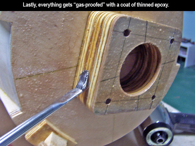
Lastly, I find that dark cockpits like this one will collect a lot of heat in the summer sun, damaging the cockpit and causing the canopy to fog up.
So, the following is the method I came up with to modify the JDM 190 for a sliding cockpit. Note that I only want to be able to manually open and close it when needed. I don't have any great desire to have it mechanically or pneumatically operate from remote control. That would open up yet another can of worms, add weight, add cost and I simply don't have the room for the required hardware. Now, let's get started... |
|
Building the framework
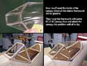
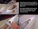
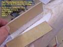
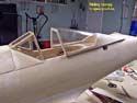
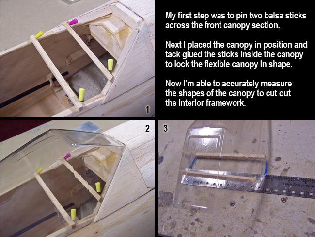
The first task was to build the interior framework of the canopy, and the first step was to pin two balsa sticks across the front "windscreen" canopy section. Then I was able to tack glue them to the inside of the canopy after placing it in position on the fuse.
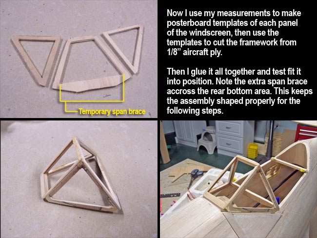
After removing the canopy and balsa sticks together, the canopy was "locked" into proper shape and spread so I could take measurements and make templates that helped me to cut accurate frame sections from 1/8" aircraft ply.
Once the framework was cut for the two sides and rear of the windscreen I was able to glue it together and test fit it on the fuse. Note that I left an temporary "span brace" in the bottom rear area of the windscreen framework. This would keep the assembly spread out into the proper shape and width for all subsequent steps.
|
|

|
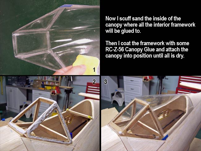
Before gluing the canopy down onto the windscreen frame, I had to scuff sand the inside of the canopy in all the areas that would end up gluing to framework or fuselage. Otherwise, the glue won't be able to "bite" into the canopy and good adhesion will not take place.
After tack gluing the windscreen framework into position, I liberally applied RC-Z-56 Canopy Glue to it and then affixed the canopy. Note that I will not actually cut the canopy into two pieces for quite a some time. The longer keep it in one piece, the better my chances are that everything will line up when the entire task is complete.
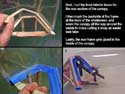
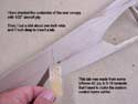
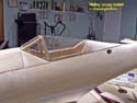
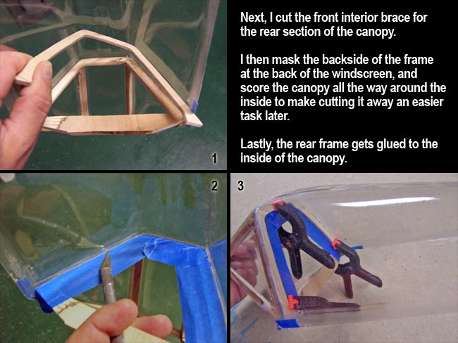
Moving on to the front framework for the rear (sliding) canopy section, I cut the framework from 1/16" aircraft ply and test fit it. Before gluing it in position inside the canopy, I had to first mask off the back side of the front canopy framework. Otherwise the two framework sections could end up gluing together and I'd have a difficult time separating them.
I also score the inside of the canopy with a razor knife all the way around the back edge of the front canopy section. This will make it much easier for me to cut the canopy into two pieces later on. Once that is finished, I go ahead and glue the frame for the rear canopy into position flush against the front section.
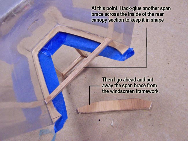
Next, I add a balsa stick across the rear canopy frame to keep it space properly, then remove the extra span brace from the front section (windscreen) framework.
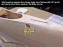
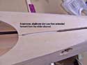
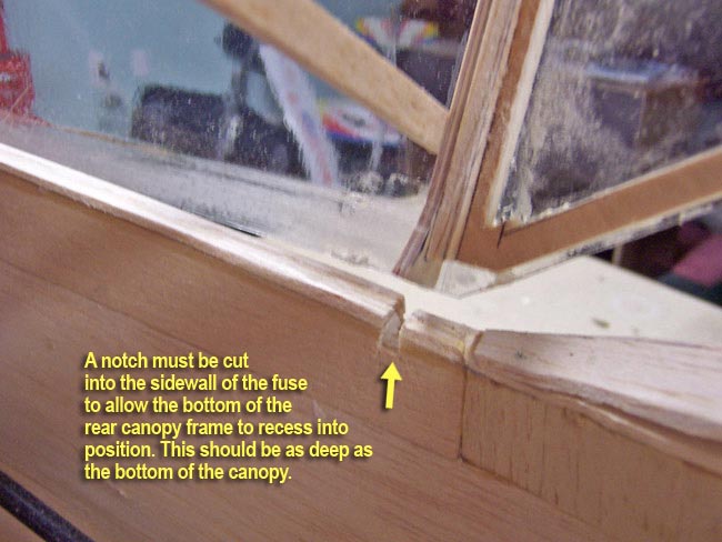
Lastly, I cut a small notch into each side of the fuselage to allow the front frame of the rear canopy to recess down into the fuse. This should allow the framework to extend all the way down to the bottom edge of the actual canopy. |
|
|
Cutting out the rear section
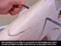
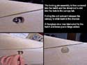
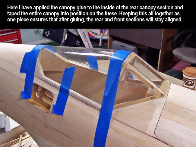
Now I need to attach the entire assembly to the fuselage so I can cut away the rear turtledeck area. I used the RC-Z-56 Canopy Glue to attach it to the turtledeck area and all the way down the sides of the fuse along the cockpit.
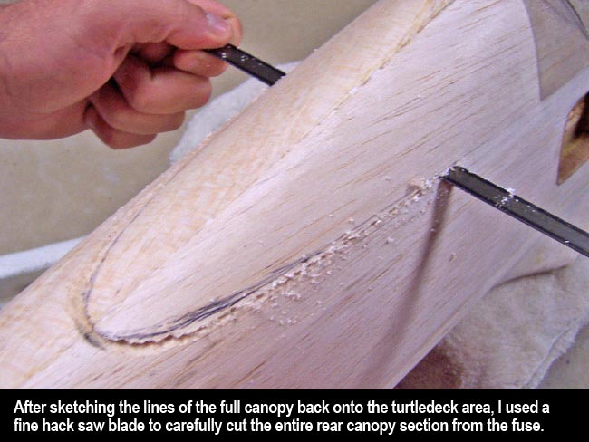
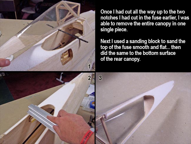
Now that the glue has set, I can start cutting the entire canopy back off of the fuse in one piece. After sketching out the cut lines on the fuse with a pen, I used a fine tooth hack saw blade to slowly and carefully cut along the lines from end to end of the canopy. The cut finishes where it meets the two small notches cut into the fuse earlier.
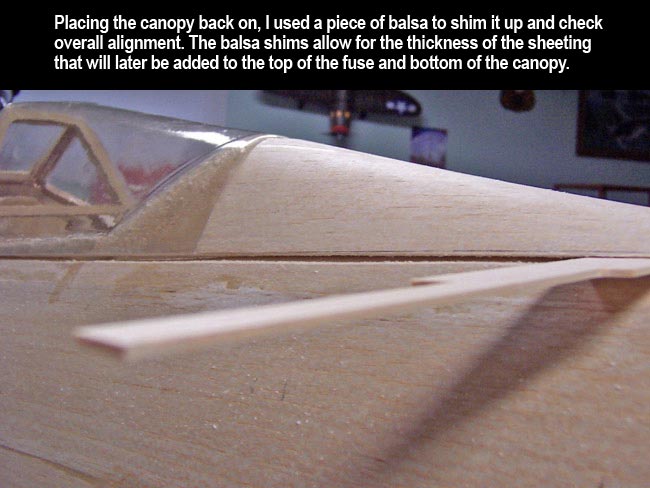
 Pulling the one-piece canopy assembly away from the fuse, I sand the exposed foam surfaces until they were very flat and smooth. I test fit it back to the fuselage using small balsa shims to space the canopy up off of the fuse a bit. This allows for the thickness that will be added when I sheet the underside of the canopy and the top side of the fuse later. Pulling the one-piece canopy assembly away from the fuse, I sand the exposed foam surfaces until they were very flat and smooth. I test fit it back to the fuselage using small balsa shims to space the canopy up off of the fuse a bit. This allows for the thickness that will be added when I sheet the underside of the canopy and the top side of the fuse later.
|

|
|
|
Fabricating the main slide channel
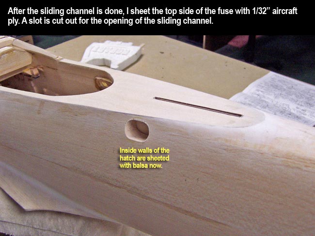
Now I start adding the components that will facilitate the sliding feature. But first, I have to sheet the bottom side of the rear canopy using 1/32" aircraft ply. This thin surface is very hard/durable but very light.
Then I was able to cut a slot in the bottom of the canopy to insert a slider tab into. The tab I made was about one inch wide and sticks a little more than an inch into both the canopy and the fuselage. The tab was made from some leftover laminate that I had made earlier for my custom control horns. It's a piece of aircraft ply sandwiched between two pieces of G-10 composite.
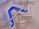
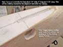
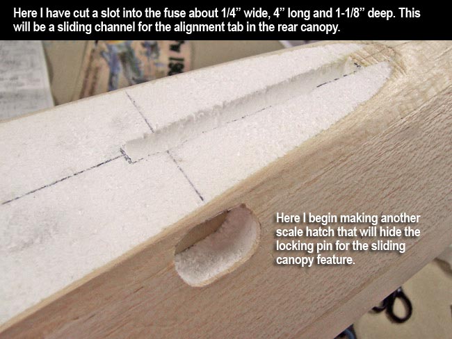
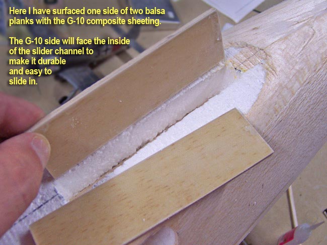
After installing the tab into the canopy with Gorilla Glue, I cut a slide slot into the top of the fuselage. The slot is a little more than 1/4" wide, about 4" long and 1-1/8" deep. The slot needed to be lined with something that would be very hard and durable, yet light. So I took two balsa planks about 1/8" thick and surfaced them on one side with the G-10 composite sheeting. With the G-10 sides facing inward in the slot, I have a hard surface in the slot that will be resilient and allow the tab to slide smoothly.
I also began cutting out another scale hatch that would allow me to hide the locking pin for the slider tab. The idea is that if I have some sort of locking pin (I used a dowel) that would slide through the fuse, into the slide channel and through the slider tab on the canopy... this would lock the rear end of the canopy down when closed and keep it from sliding back as well.
Like on the other hatches I've installed on this plane, I had to permanently glue a thick AC ply "bulkhead" deep inside the hatch hole. This gives me a strong support to slide the locking pin/dowel through. |
|
|
Installing the slider lock pin
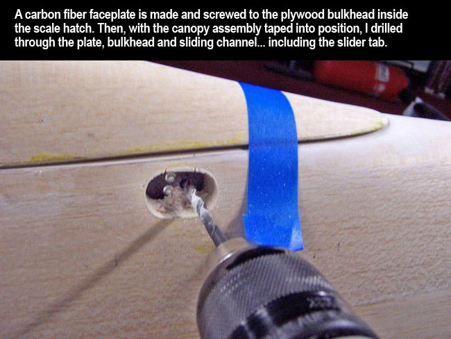
Also like the other hatches on the plane, I install all hardware in a carbon fiber faceplate that is screwed to the ply bulkhead. This allows me to easily remove, change and/or service any hardware in the hatch.
I start by installing the CF faceplate and drilling a hole through it, through the ply bulkhead, through the sliding channel walls, and through the slider tab on the canopy. Obviously I do this step with the full one-piece canopy slid all the way forward in final position.
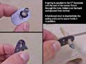
Now I pull the CF plate back out of the hatch and epoxied a small spring to the front of it. Note that I also folded back a small section at the base of the spring so I could pull it through the hole and glue it to the backside of the CF plate. This will add a lot of strength to the glue joint holding the spring to the CF plate.
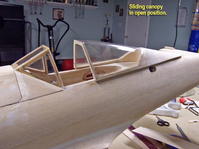
I then slid a dowel rod through the back of the CF plate and up into the spring. I secured it by adding a servo screw into the end of the dowel, pinching the end of the spring. With the canopy slid into "closed" position, I was able to then install the entire locking pin assembly inside the hatch. By pulling the end of the dowel out about half an inch, it releases the slider tab and allows the canopy to slide back into the "open" position.
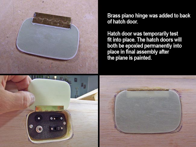
Lastly, I added a small hatch door from scrap fiberglass from the engine cowl. This door, like the others, got a small brass piano hinge. Permanent installation will take place after the plane has been painted.
|

|
|
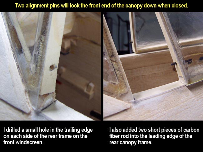
Alignment pins
While the slider tab does a pretty good job of holding everything in place, additional alignment pins were needed to make the canopy slide straight, and also to lock it down up front where it meets the front windscreen section.
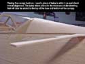
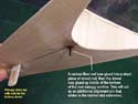
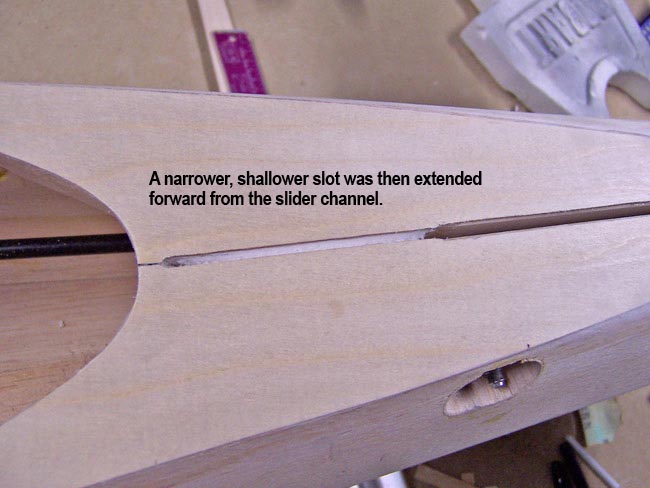
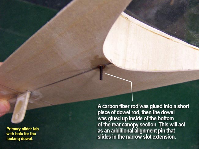
To facilitate this, I first added another slide slot that extends forward from the first slot. This one is narrower and shallower than the first. Also, it does not get surfaced like the first slot did. I then inserted a piece of carbon fiber rod into a small section of dowel rod, then glued the dowel up into the underside of the rear canopy. This pin slides in the narrow slot that was extended forward from the main slide channel. This adds a great deal of torsional stability to the assembly while also helping to keep everything "on track" when sliding back and forth.
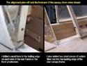
Now it's time to go ahead and us a razor knife to cut the front and rear sections of the canopy apart. The scoring from the inside will make this much easier to accomplish. Lastly, I added a couple small carbon fiber pins to the front edge of the rear canopy frame. I also drilled two holes in the rear edge of the front windscreen section. As the canopy slides forward and locks into position, these two pins slide into the holes and lock the front end of the canopy down.
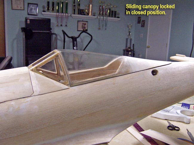
With the big locking dowel inserted at the rear of the canopy, it is held down at the rear, and is also pushed tight up against the windscreen. Then the two alignment pins at the front do the job of holding the front end down onto the fuse. The finished assembly is very secure and has very little slop in it. |
|
Final steps
Once everything was fabricated and/or installed, the last thing to do was to fine tune the sliding and adjust anything as necessary for efficient operation.
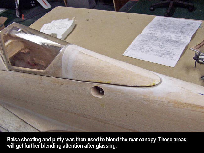
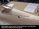 The canopy also needed to be blended into the turtledeck. To do this I glued a 1/2" strip of 1/32" balsa sheeting to the turtledeck, butting it up against the trailing edge of the canopy material. This would minimize the need for putty and make it easier to blend the step down from the canopy material into the balsa sheeting. The canopy also needed to be blended into the turtledeck. To do this I glued a 1/2" strip of 1/32" balsa sheeting to the turtledeck, butting it up against the trailing edge of the canopy material. This would minimize the need for putty and make it easier to blend the step down from the canopy material into the balsa sheeting.
After sanding the area to blend, I added some balsa putty to further feather it out and sanded again. I also used some balsa putty to better feather the fuselage balsa sheeting into the new 1/32" AC ply sheeting that is surfacing the top side of the fuselage.
Once I glass the plane, all these areas will get further putty and sanding work until it all blends and feathers well and is very smooth and level. |
|
| |
|
|
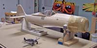
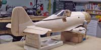
Finished and ready for glassing
Well, that's it for primary airframe construction now... the plane is pretty much ready for the application of fiberglass. Of course, I'll first have to spend a few nights going over everything carefully to make sure all putty work is done and everything gets sanded as smooth as possible.
I'm not sure yet what I'll be using to apply the glass cloth, but you can bet it will be a water-based Polycrylic material. I've used MinWax in the past, but I'm contemplating some other brands as well. I'll probably spend some time soon doing some new technique and material tests before moving on to glassing. |
|
|

"glassing, detailing and painting"
|
|


