|
Sept 16 , 2006
 |
| |
|
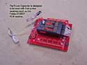
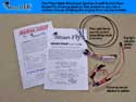
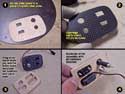
Smart-Fly "Power Expander Pro "
This section covers the majority of the miscellaneous hardware and electronics that remain to be installed inside the fuse... much of which are high quality electronics from Smart-Fly. All of these components can be purchased at the www.smart-fly.com web site.
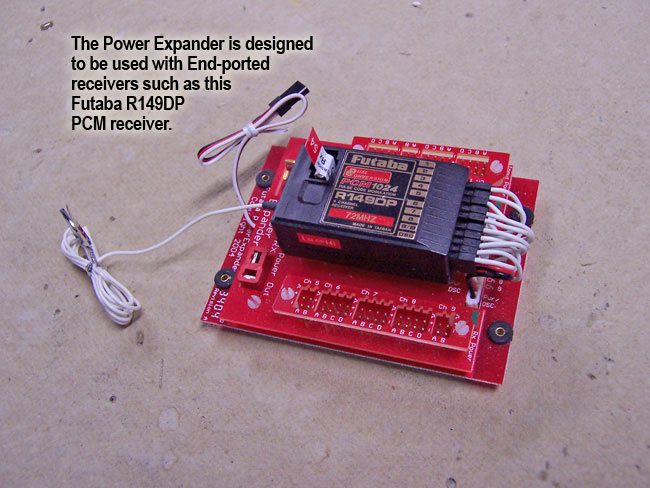
The first component to cover is the Smart-Fly "Power Expander Pro" unit. This device is what you'll mount your receiver to, and plug your servo leads into. This will provide your receiver with a clean 5 volts of power while still pumping the full voltage of your battery to the servos. In the case of my giant scale planes, that's always going to be a regulated 6 volts of power for optimum torque. The Power Expander also makes sure that the amp loads are distributed and handled in such a way that voltage drops to multiple stalled servos is nearly eliminated.
|
|
|
The Power Expander Pro has multiple ports for each and every one of the 9 PCM channels, so this may help avoid Y-harnesses in your installation if you choose to utilize this feature. The 10 servo lead pigtails on the Power Expander plug into your receiver (9 channels plus power). This unit is designed to work with "end-loading" receivers such as the Futaba R149DP PCM receiver that I am using here.
| There are actually three Power Expander models, the Sport, Pro and 14mz. The Power Expanders use Deans' Ultra connectors for input power resulting in the ability to deliver in excess of 30A of power to the unit. The power is distributed to each servo through a high current buss that results in negligible voltage drop to each servo. In addition, the input power is regulated to 5.0V and filtered before it is delivered to the receiver. All signals in and out of the unit are RF filtered resulting in extremely clean operation. The units also include long-extension matching which results in a cleaner signal to the servos and less RF noise. The Power Expander provides status LED's that indicate power from the battery is on and power to the receiver is on. |
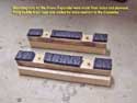
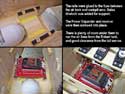
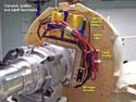
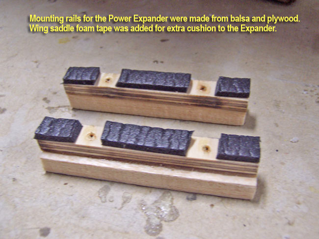
To install my PE unit, I built two mounting rails from aircraft ply and balsa. I also added some pieces of wing saddle tape to aid in cushioning the unit to the rails. I then glued these rails onto the "ceiling" of the fuse between the air tank and the cockpit. With the plane upside down, this puts the PE unit directly below the servo tray for the tail. It also raises the unit off the balsa sheeting so that the air lines from the Robart tank have plenty of clearance to pass underneath it. The PE Pro unit is then mounted to the rails via four servo screws running through the four mounting grommets built into the Power Expander board.
|
|
|
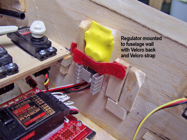
Smart-Fly "HD Regulator w/Failsafe Switch"
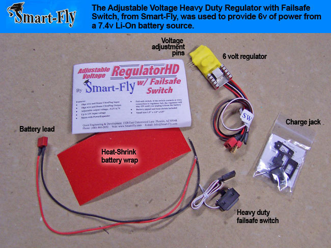
Next is the regulation of the battery power that gets sent to the Power Expander. For this I always use the Smart-Fly "Heavy Duty Regulator with Failsafe Switch." This gives me a good regulated 6 volts of power to the PE Pro unit and the peace of mind that comes with a failsafe RX switch.
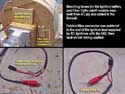
The heavy-duty regulator has Deans UltraPlug connectors and 18 gauge wire on both the input and output sides. These regulators are for connecting to certain Smart-Fly components that have Deans connectors and other manufacturers that have Deans UltraPlug connectors on their units.
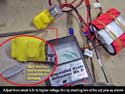
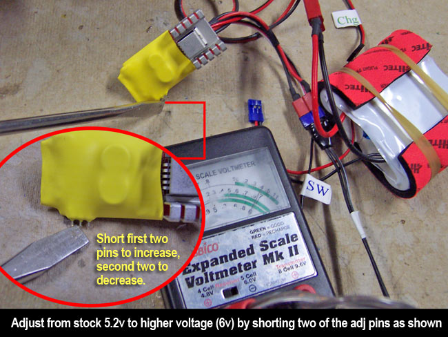
The regulator also comes with a Deans power lead and heat-shrink wrap for your battery pack. These regulators are adjustable from 5.2 volts (default) up to 6.7 volts by shorting out two of the three adjustment pins on the side of the regulator. Using something metal (like a screwdriver), just jump the first two pins together to increase the voltage, and the second two pins to decrease the voltage.
The longer you jump them, the more it adjusts... at a rate of about 1/4 volt per second. You can monitor the voltage while adjusting by simply plugging in a voltage meter to the "Power Out" Deans lead while adjusting (with battery connected to "Power In"). I used a standard Hobbico voltage meter with it set for a 4-cell 4.8v receiver battery. Mine immediately read 5.2 volts, and I easily ran it up to an even 6.0 volts using the jumper pins.
Designed specifically for 7.4 volt Li-on packs, this unit gives you a great way of regulating the voltage to your receiver or Power Expander. It also has a heavy duty failsafe switch that always failsafes to "ON" if the switch goes bad for any reason.
|


|
|
|
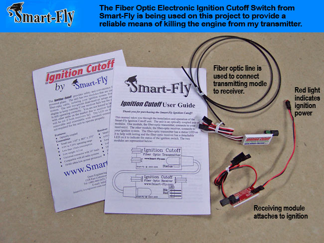
Smart-Fly "Fiber Optic Ignition Cutoff"
Now we move on to the Smart-Fly "Fiber Optic Ignition Cutoff" that I also always use on my gasoline engines. I am a firm believer in always having a way to kill your engine from the transmitter, especially when we're talking about gasoline engines that can run a long time should your throttle linkage ever come loose, or throttle servo go bad. Since I prefer electronic ignitions on my gas engines, this makes for a great match with the Smart-Fly Fiber Optic Cutoff.
The risk of connecting anything between your electronic ignition and radio receiver is that RF from the spark plug/ignition can easily travel back down any wires to your receiver (disaster). So, the Smart-Fly unit uses Fiber Optic cable to connect the two, eliminating any possible RF transmission down the line. It uses less than 15mah to operate, is very light, and operates on a wide range of voltages. It also comes with a detachable red LED bulb that lets you know when power is being supplied to your ignition.
 I usually have both this Fiber Optic switch installed, as well as a standard MPI manual switch somewhere on the plane. Both need to be turned on in order for the ignition to be powered. This way I can quickly kill the ignition power on the ground or in the air from either switch. I usually have both this Fiber Optic switch installed, as well as a standard MPI manual switch somewhere on the plane. Both need to be turned on in order for the ignition to be powered. This way I can quickly kill the ignition power on the ground or in the air from either switch.
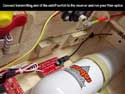
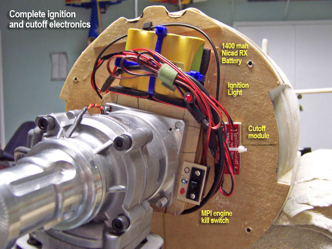
After installing the "transmitter" module of the cutoff inside the fuse, I run the fiber optic line through the firewall and out to the "receiver" module on the firewall. Mounting boxes are installed as needed on the firewall to house the modules and the 1400 mah 4.8v NiCad ignition battery.
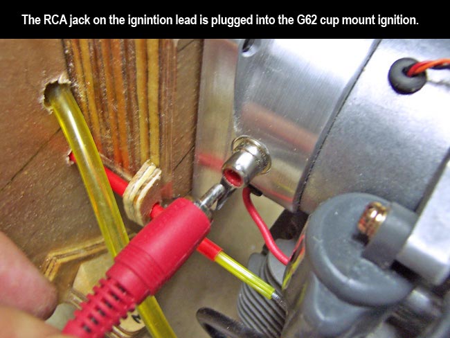
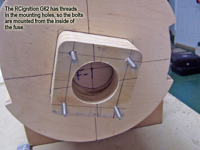
I solder a Futaba/Hitec plug onto the ignition cable that came supplied with my RC Ignitions G62 engine, then connect it to the Fiber Optic receiver module. The other end of the ignition lead is an RCA composite jack (like on stereos) which plugs into the side of the custom cup mount/ignition combo pre-installed on the G62.
I actually run the power from my battery to the manual MPI switch first, then from that it goes to the Fiber Optic receiver module, then on to the ignition. So, cutting the power on the MPI switch actually cuts the power to the Fiber Optic switch. I normally program the Fiber Optic switch to channel 5 or channel 8 on my transmitter.
The only other thing left to do is come up with some sort of pushrod to the MPI manual kill switch that will stick outside of the cowl in an inconspicuous position. I'll work that out later.
|
|
|
 |
|
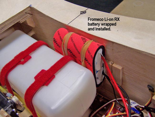
Fromeco "Peerless Li-on"
receiver battery
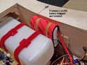 All my giant scale planes get 4-cell 7.4 volt Lithium Ion packs from Fromeco Scale Avionics. I normally use their standard Fromeco "Relion" packs but am going to be testing out their newer and more advanced "Peerless" battery on this plane. All my giant scale planes get 4-cell 7.4 volt Lithium Ion packs from Fromeco Scale Avionics. I normally use their standard Fromeco "Relion" packs but am going to be testing out their newer and more advanced "Peerless" battery on this plane.
The "Peerless" packs are an upgrade from their previous "Relion" line in nearly every respect, including cell balancing and the addition of new state-of-the-art electronics.
For an extensive review of the Fromeco "Peerless Advantage" click here.
|
| |
|
|
Retract air valve and servo
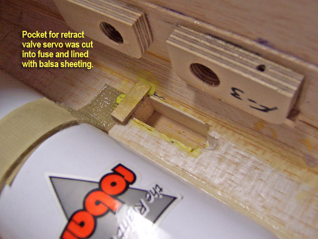
Next up is the air valve for the retracts and the servo that drives it. I use the Robart "Deluxe" air system and valve which allows for easy adjustment of the air pressure to in and out lines. After determining where everything was going to fit and operate without obstruction, I moved on to installing the servo first.
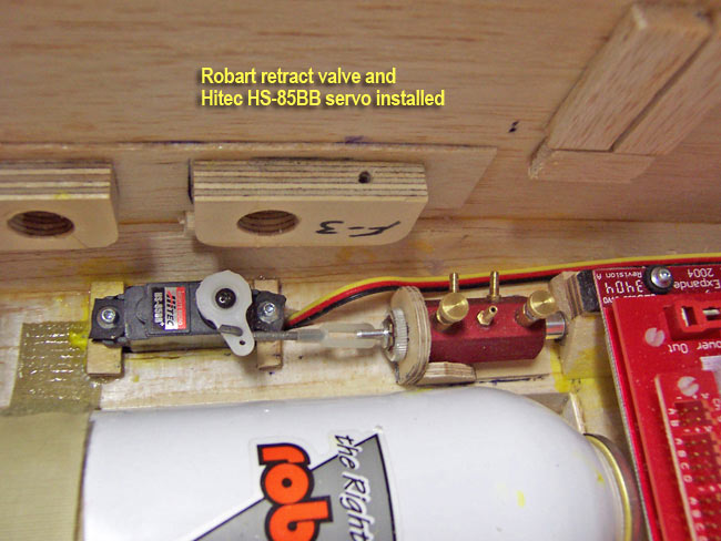
Like I did with the throttle servo, the retract valve servo gets installed in a "pocket" cut into the styrofoam wall of the fuse so that it uses minimal space. After cutting the rectangular pocket out and lining it with balsa sheeting, I could then drop in the Hitec HS-85BB servo.
Using a short 2-56 metal pushrod, I connected the servo to the valve. The valve is mounted to the fuse via mounting plate made from AC ply. The plate gets glued to the fuse, but the valve and servo can easily be removed as needed.
|


|
|
Fabricating hatch doors
It can be difficult to install all the switches, jacks and valves for a project like this such that they are hidden and not cluttering up the scale appearance of the plane. The usual answer is to find some scale hatch locations on the real plane and make them functional on your model. This gives you a few places that you can hide the necessary evils behind hatch doors.
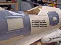
On this 190 project, I'll be fabricating two hatch doors. A small one up front below the gun hood will hide the actual fuel filler hardware. A larger hatch on the side of the fuse between the wing fillet and rear canopy will be home for just about everything else that needs hidden.
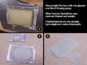
You can easily use the "fiberglassing over Monokote" technique that many of us use to lay up hatches and gear doors (as shown here). However, I decided to try something different out again. I taped two pieces of my thin (about 20 mil) G-10 composite/phenolic material onto the contour of the fuse over the two scale hatch locations.
I then glassed over these pieces with heavy duty fiberglass cloth and epoxy resin. Once it was built up enough, I remove them, sanded them and cut them to shape. The end result followed the contour very well, was very stiff/strong, and quite light. |
|
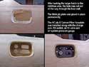
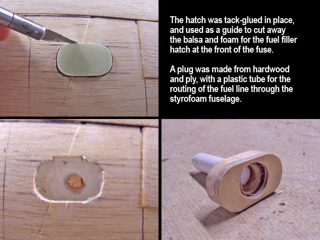
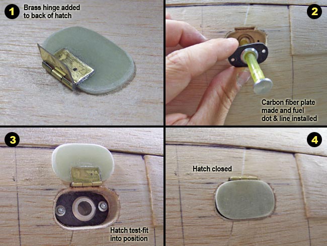
Fuel filler hatch
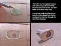
Fuel filler installation begins with tack-gluing the hatch door to the side of the fuse and cutting out the sheeting around it. Remove the hatch, the sheeting and dig out the foam about an inch deep. Next I drill out a hole through the remaining styrofoam a little larger than the Tygon fuel tube diameter.
Then I make a ply plug with the center drilled out and an alignment sleeve glued to it (made from plastic tubing). This will fit down in the hole dug out of the foam and extend through to the fuse interior. The surface of the plug has a larger diameter hole recessed into it to allow for the filler nut. The plug gets permanently glued down inside of the fuse wall.
Next I glue a small brass piano hinge to the back of the hatch door. A little mounting plate is cut from carbon fiber plate and drilled out to receive the fuel filler and fuel dot. The filler is tightened onto the CF plate and it all gets mounted to the plywood plug via two servo screws.
The hatch door is then test fit and will be permanently epoxied in place after glassing and paint. This technique allows me to easily remove the assembly via the two screws, back the nut off, and do any required replacement or maintenance. |

|
| |
|
|
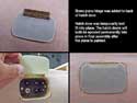
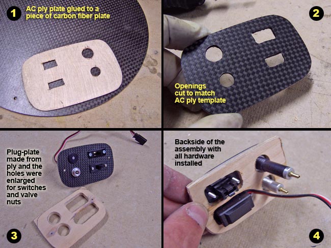
Hiding switches and valves
The same basic technique is used for the larger hatch in the mid-section of the plane. This hatch will house four items... the receiver switch; receiver charge jack; air fill valve; and air pressure gauge.
I start by cutting a thin AC ply plate about the same shape/size as the hatch door. I add small cutouts to allow the four components to stick through it. I then glue this plate to a piece of carbon fiber plate and cut the assembly out. I then open up the same four holes through the CF plate.
With the sheeting and foam cut out of the fuse behind the hatch door area, I make another thicker plywood plate that will fill the hole. This plate glues permanently into the hole, recessing at an angle about half an inch deep in the hole. It also has four holes cut out for the for items to be installed, but these holes are larger. They allow the entire mass of the four switches/valves to pass through it to the inside of the fuse... including any mounting nuts.
The four components then get installed in the carbon fiber laminate plate and slid into position in the hole, over the ply backup plate and it all gets screwed together with two servo screws.
|
|
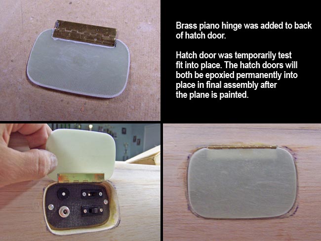
Like the fuel filler installation, the hatch door gets a brass piano hinge, which is test fit into position and removed for permanent epoxying after glassing and paint.
Once again, this method provides a means to easily remove the CF mounting plate via the two screws so that I can pull and repair/replace any of the four components, without needing to get up inside the fuselage to do so.
That's it for now. Additional steps will need to be taken to add all the remaining wiring and plumbing that hooks all this hardware up. But, I'll wait until the plane is finished to do this... for now I'm about ready for airframe fiberglassing. But first, what to do about that canopy? I think I still need to work that out before proceeding with glassing. |
|
|
|

"sliding canopy mod"
|
|


