|
Williams Brothers wheels
Before going over the retract installation, I first want to cover the topic of wheels. In order to properly fit your retracts, you'll need to get your wheels temporarily mounted so you can test alignment and fit in the bays as you cut them out.
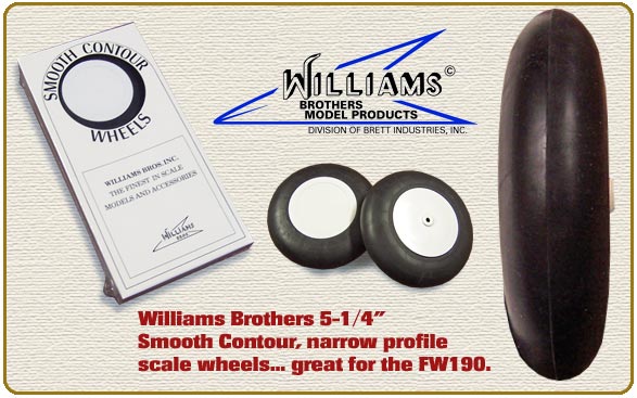
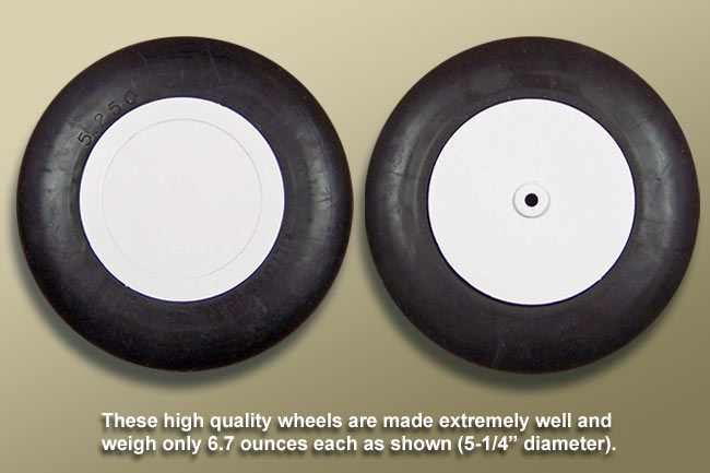
I chose to go with the 5-1/4" Smooth Contour wheels from Williams Brothers Model Products. This awesome model specialty company has a great line of scale wheels of many sizes and styles. Their wheels are of very high quality at an affordable price.
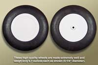
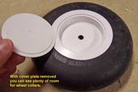
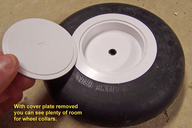
The Smooth Contour wheels I am using have a very narrow profile like the FW190 requires for fit and scale appearance. I found the foam-filled rubber construction to be quite light for large scale wheels at 6.7 oz each. The hub is a very strong plastic, including the removable smooth cover on one side. Removing the cover you will find plenty of room for the wheel collars on the axle.
Speaking of axles, another nice thing with these wheels is that they fit the axle of the Shindin retracts perfectly as is. No need to enlarge the axle hole or even cut the axle length down to get the cover plate on. I highly recommend these wheels. To see these wheels getting some scale details added, click here. |
|
|
Laying out the main gear installation
Now we get to the actual installation process... well almost. First I had to plan out how the gear were going to fit into the wing by checking the 3-views for proper scale position, while simultaneously trying to figure out if they would fit within the wing as such. To make a long story short, this proved to be somewhat of a challenge as I had to repeatedly change my plan as I went along. I'll explain more on that later.
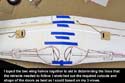
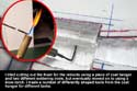
Basically what I needed to accomplish here was where my retracted gear would position on each wing half so that I could get the wheels to fit entirely into the wing, and, so that the struts would present the proper angles when extended. I began by taping the two wing halves together and sketching out the silhouette of the retracts, wheels and gear door shape. The key points I needed to lock down were where the axle would hit in the wing and where the end of the air cylinders would position. These landmarks would establish positioning left, right, fore and aft, as well as determine the overall line the struts would lay within the wing.
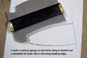
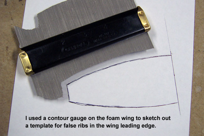
After getting this layout as close as I could without actually cutting anything, I went ahead and used a Contour Guage to create a paper template of the forward airfoil shape where the gear blocks would mount. This would permit me to cut ply false ribs out later for gear bay construction. |
"Hogging out the foam"
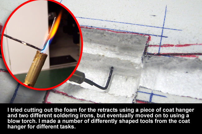
Now comes the "fun part"... removing the styrofoam for the retract installation. To do this, you need a hot wire that you can scoop or "hog out" the foam with. The best thing I have seen is just a common coat hanger. Some guys use a piece of it inserted into a soldering iron, which I tried with two different irons but didn't care for it. I just couldn't get the wire hot enough with a wire that was any longer than an inch or so. Therefore I ultimately changed over to using a blow torch and fashioned a few different burning tools from coat hanger wire for different cutting tasks.
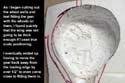
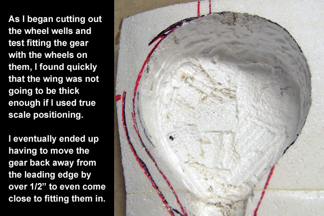
The pictures at right show some of the foam removal process. Admittedly, it isn't real pretty at this point but it will all clean up fine later. The first thing I found out in doing this was that the gear and wheels were going to have to move back at least 1/2 inch into the thicker chord of the wing or else they'd never fit. I cut styrofoam out until I was coming out the top side of the wing nearly everywhere but still couldn't get the gear to fit down in all the way so I ended up moving the cutouts back away from the leading edge until they did.
However, this won't leave me any room for adding wheel well detail, and I still will have a challenge figuring out how to get the gear door down flush with the wing surface. I have a few ideas and will cover that topic later on another page. Suffice it to say, after cutting and fitting, cutting and fitting, and cutting and fitting some more... I eventually got the retract cutouts complete. I'll still have to open them up further to the shape of the gear doors later, but for now, this will do until after sheeting is complete.
|
|
|
Building the retract mounts
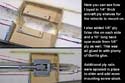
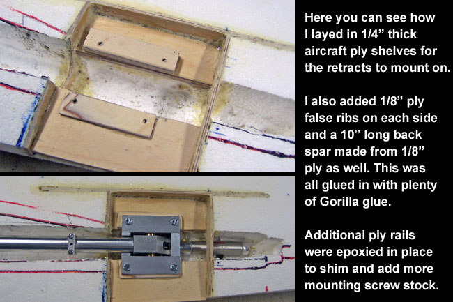
To build the retract mount area up, I cut the foam down to a recessed shelf which is about halfway down into the wing. I applied 1/4" aircraft ply to these shelves on both sides of the retract channel. I also used my template to make two 1/8" aircraft ply false ribs that would lay in on each side of the 1/4" ply shelves. These two false ribs had to be cut out in the middle to allow the retract air cylinder and upper struts to pass through them. One gets a "U-shape" cut out of the top and the other gets cut out of the bottom.
Both of these two false ribs also extend back to a 1/8" backup spar that runs 10" lengthwise in the wing, right against the backside of the 1/4" shelves. When all this ply is glued in place with polyurethane "Gorilla Glue" it forms a strong box that distributes stress over a large area of the wing. The spars and ribs go almost all the way through from top to bottom of the wing too. The Gorilla Glue foams up after a short while and fills back into any uneven surfaces or gaps in the foam giving you a rock hard joint even in the messiest of situations.
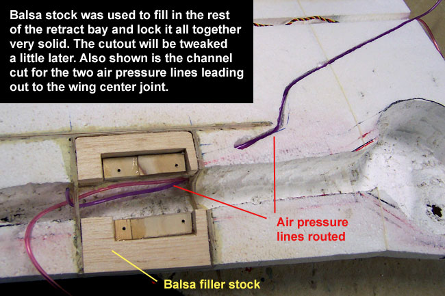
I then filled up the remainder of the gear bay with balsa blocks and sanded them down to the airfoil contour, flush with the wing bottom surface. When that gets epoxied in, you have a very strong and solid retract mounting foundation. Lastly I added some aircraft ply rails on top of the shelves to shim the gear to proper position/angle as well as provide more "meat" for the retract mounting screws to thread down into. I will be using 1" sheet metal screws to secure the gear to these rails.
Lastly I used a drill and my hot wire to cut a channel in each wing through the false ribs and across the wing back to the aileron lead channel. This new channel is for the two air pressure lines that will run from the retract cylinder to the air valve and system in the fuse. The installed pressure lines fit snugly down into a recessed channel now that keeps them just below the bottom wing surface. I will be using the Robart Deluxe Air System with the Medium Size air cylinder. |
Summary
To summarize this part of the retract installation, let me clarify a few points. While the wing is just a little too thin on this specific kit to get the retracts to fit into proper scale position, I'm really not all that far off. Plus, on other kits it may not be an issue. Also, I could almost get the gear to completely fit without any serious modification if I chose not to use the scale standoff brackets and scissors. But, I want to use them so I'll have to come up with a workaround to deal with about 1/8 - 1/4" of unwanted space that could be between my gear doors and wing surface when retracted. I'm not worried about it, I'll come up with something.
The main thing you want to remember as you go through the above steps is that you need to keep both wings the same. In other words, if your gear are out of postion or off-angle slightly it's OK as long as they are both off the same amount and direction. Of course, you don't want the gear to get out of position too far or you could run into balance/CG problems or ground handling problems.
These Shindin gear have no forward rake built into them, so be sure to try to rotate the retracts forward in the wing such that you get as much forward rake as possible. Ideally you'd want the extended gear to be in front of the leading edge of the wing, but you won't be able to rotate them that far with this kit without popping out through the top of the wing when retracted. Just rotate them until the wing airfoil won't permit any more and stop there.
NOTE: Forward rake can be added as an option if requested when ordering your gear.
Then, constantly be checking where the axle and tip of your air cylinder are positioning in each wing to make sure both wings match. Also measure the depth of the retract hinging armature at all 4 screw holes to see how deep each corner of it is within the wing. Matching these depths from one wing to the other will help ensure that both your gear present the same angle when extended..
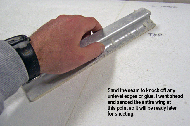
On later pages I will go on to cover the rest of the retract installation which includes the air system, adding additional scale detail, painting and final/permanent installation. Next up is capping the wing before sheeting begins.

|

