|
Nov 15 , 2006
The goal
 Let me start this section by first explain what my goals and expectations were for my control surfaces. Remember first, that unlike a stick-built construction, these control surfaces are balsa-sheeted foam cores, just like the rest of the plane. So, there really isn't any fabric covering involved here like there would be on a stick-build or the full scale plane. Let me start this section by first explain what my goals and expectations were for my control surfaces. Remember first, that unlike a stick-built construction, these control surfaces are balsa-sheeted foam cores, just like the rest of the plane. So, there really isn't any fabric covering involved here like there would be on a stick-build or the full scale plane.
That being said, I wanted to give it some sort of surface detail that would at least make them "appear" different than the rest of the plane, and in doing so, try to look somewhat like the real fabric covered control surfaces. I'm not going for competition level accuracy, but just flat, smooth surfaces would not make muster with me on this plane.
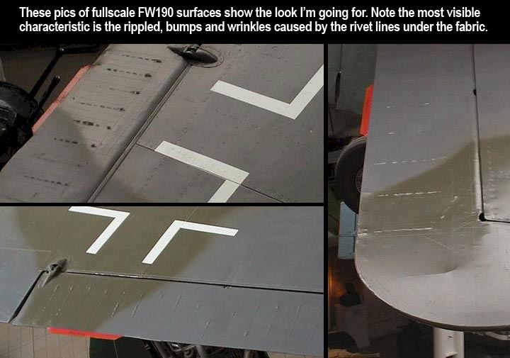
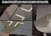
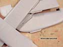
Now, let's take a look at the photos of a full scale plane here at top right. These images show what I'm accustomed to seeing on most fabric covered control surfaces. Note that the the rib stitching is barely visible, and at this range, the pinking of the edges is virtually undetectable. Note also, that the actual texture of the fabric is not perceptable, only the stretched tenting lets you know it's fabric. What you DO find very noticeable are the random bumps, wrinkles and ripples on top of each rib.
These "ripples & wrinkles" as I'll call them are the single most noticeable characteristic on almost any fabric control surface I've seen... yet as modelers, I've found that virtually none of us replicate this feature. Furthermore, I believe we go way overboard simulating the cloth texture and pinked edges. Again, at a distance of 10 feet, you can see that these features are somewhere between subtle and invisible. Yet, many scale modelers insist on having these details strongly visible at 10 feet, which multiplies out to a scale viewing distance of 50-60 feet! Sorry, you just won't see them at that distance.
I also feel that any pinking you do (even with the new tiny pinking shears) is still not even close to scale in size. Looking at the images above, you'll see that the z-pattern of the pinking cannot even be seen... it's very small and subtle.
Anywho, off my soap box now... Here's the deal. I'm going for subtle, irregular edges to my rib stitching strips, and focusing more on the "wrinkles and ripples" down each rib or frame edge. I believe that these are caused when the rib stitching strips are place over top of the screws/rivets that fasten the fabric into each rib. That's the purpose of the rib stitching strips... to cover those rivet heads and keep them from tearing out the fabric at the stress points. So, once the strips go over the heads and the fabric gets doped up, you end up with these randomly shaped ripples. There's where I'm headed.
|

|
Stencils and masks
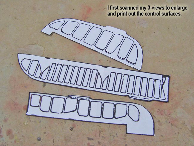
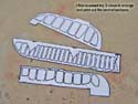
Now, let's start with the stencils, which I scanned from my 3-views, enlarged in Photoshop and printed out on paper. I then cut them out of the paper giving me a good actual size template for each of my 3 control surface shapes.
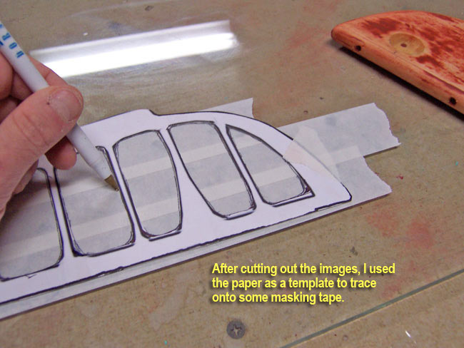
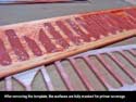
I put masking tape down on a pane of glass and traced the templates down onto the tape with a pen. Before moving on, I tape the templates into position over the top of my control surfaces.
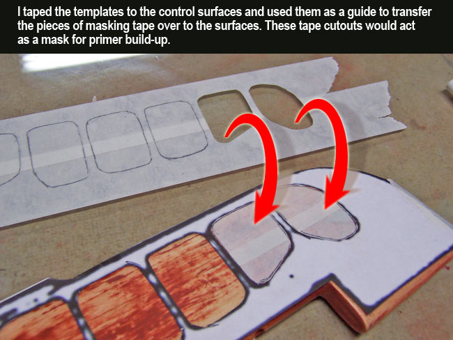
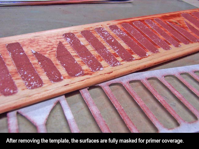
 Next I cut out the areas between the ribs and transfer them into position on the control surfaces using the template as a guide for placement. Once they are all in place, I remove the template and visually check alignment of them all in relation to one another. After adjusting slightly as needed, I'm ready for the next step. Next I cut out the areas between the ribs and transfer them into position on the control surfaces using the template as a guide for placement. Once they are all in place, I remove the template and visually check alignment of them all in relation to one another. After adjusting slightly as needed, I'm ready for the next step.
|
|
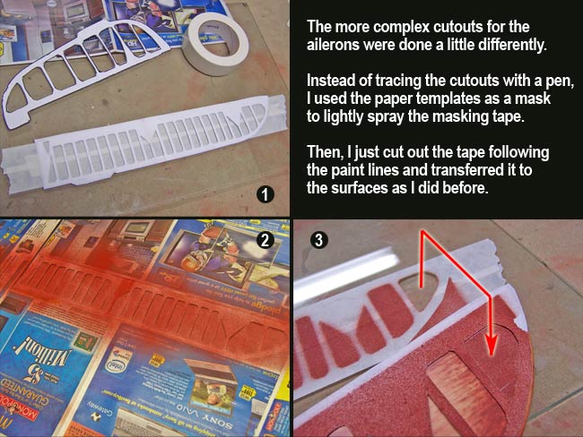
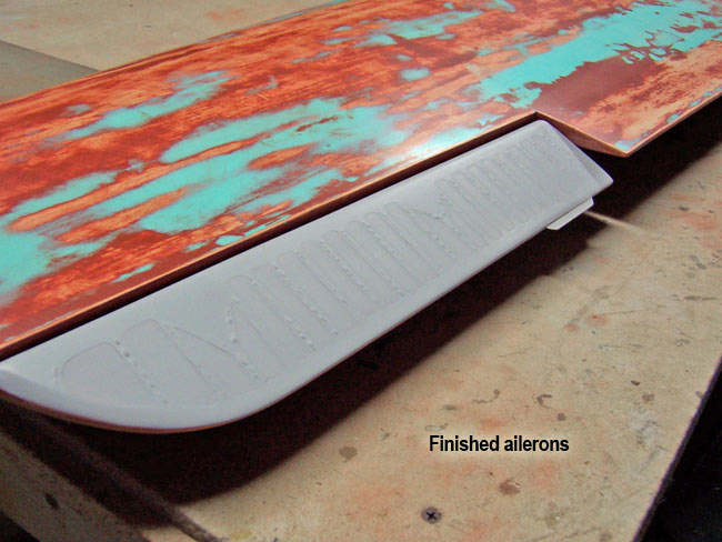
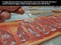
The above technique worked quite well for the simple templates of the rudder and elevators. But, the ailerons were much more complex and difficult to trace out by hand. So, for the aileron templates, I just laid them on the masking tape and very lightly sprayed a dusting of primer over everything.
Then after removing the masking I had my outlines painted on the tape to facilitate the process of cutting the masking tape out with my hobby knife. This was much easier and faster for the ailerons than it would have been had I done it with a pen. |
|
|

|
Wrinkles & ripples
Now for those interesting wrinkles and ripples I talked for so long about. I'll be honest, I'm not going for competition accuracy here, but I want them to be recognizable from a few feet away, and somewhat convincing in appearance. I don't expect anyone to get down a few inches away and inspect them with a magnifying glass (if they do I'll slap them in the back of the head LOL).
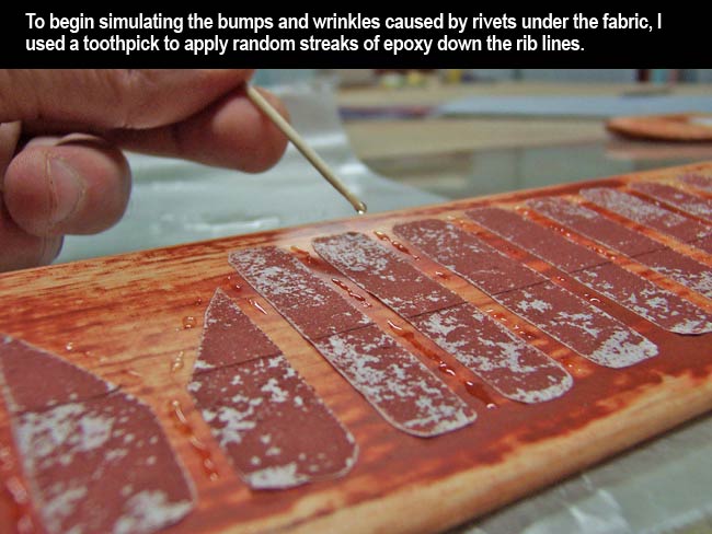
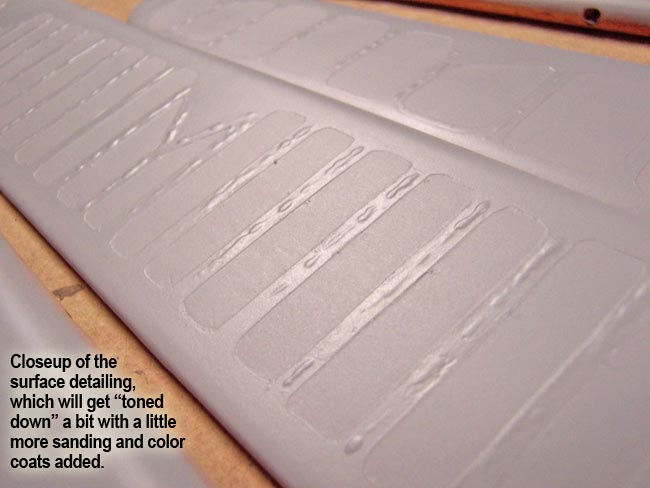
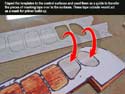
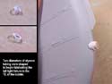
The process is ridiculously simple. I just use a toothpick to streak some epoxy into randomly shaped wrinkles down the centerline of each rib strip. Studying the photos of full scale surfaces helps a lot in determining what they should look like, and how random they are in overall appearance.
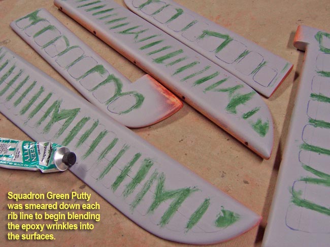
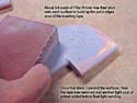
Once the epoxy dries, I smear some Squadron Green Putty over each line of epoxy. This will help blend the beads of epoxy into the surface to make them look more like bumpy wrinkles instead of epoxy.
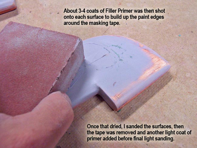
Lastly, I hit everything with about 3 heavy coats of Filler Primer. This further blends them wrinkles into the surface, but more importantly, it builds up the subtle edges around the masking tape to simulate the rib strips (much like building up panel lines).
|
|
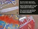
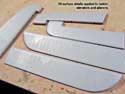
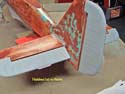
Once the primer is dry, I go ahead and give everything a light sanding with a sanding sponge, taking care not to "flatten" the peaks of the wrinkles. After that, the masking tape is removed and I give the whole surface one more light coat of primer to soften the edges of the masked areas a bit. I don't want these to be as strong as the edges of my panel lines on the metal skin of the airframe... just subtle.
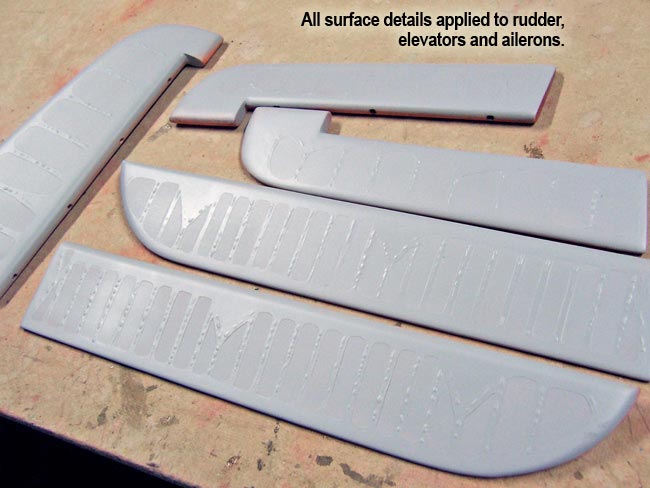
As you can see from the pics at right, these surfaces now look much more convincing than just flat, sheeted and glassed surfaces. And surprise, they don't look too terribly far from what the full scale surfaces look like. The rib strip detail is a little strong for my liking, about two coats would have been enough. But, another light sanding, the color paint coats and clear coat will do well in softening the edges up a bit more..
|

|
|

|
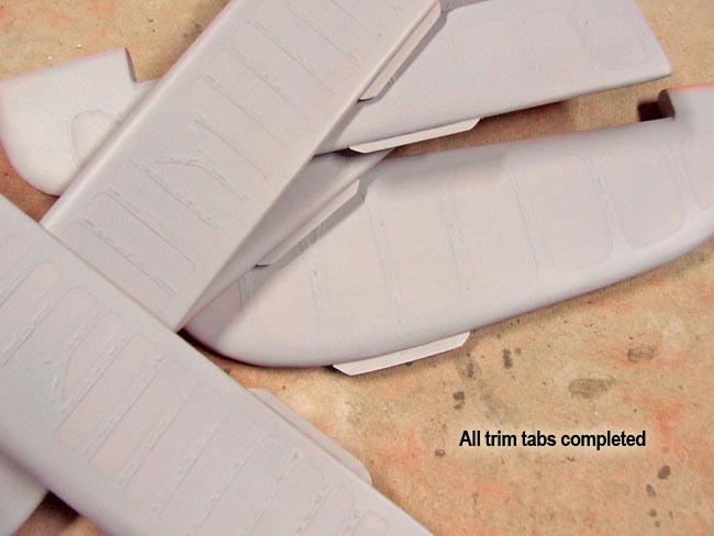
Trim tabs
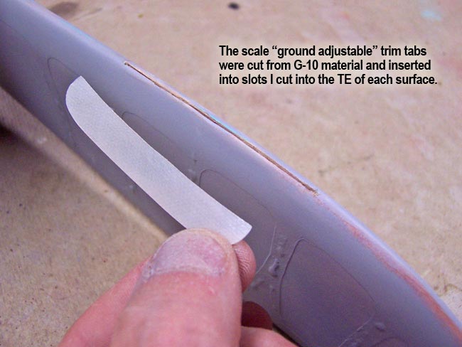
To finish off the control surfaces, I had to add the scale trim tabs to the TE of each surface. These aluminum tabs were not adjustable in flight, but rather they were bent into position as needed when the plane was on the ground.
I fabricated mine from a thin sheet of some G-10 material, cut slits into the TE of each surface, then glued them in place with some Thin CA. Very easy step of the build.
|
Tail light
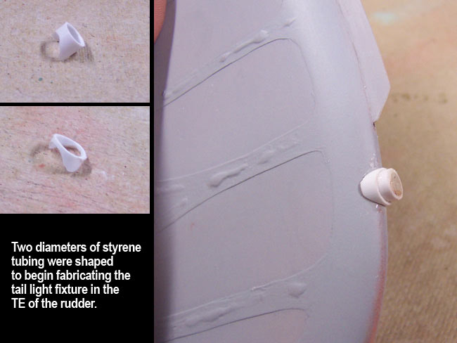
OK, I guess I have one more detail to cover... the tail light. To fabricate this detail, I took two pieces of styrene tube, one slightly larger diameter than the other. I cut them to length and shape such that they would fit flush over the trailing edge of the rudder, just below the trim tab.
Gluing the smaller one in place first, I then slid the larger over top of it and secured with Medium CA as well. I filled the center with a dowel plug.
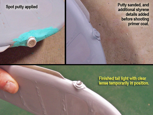
My usual steps of Green Putty, Primer and Sanding then allowed me to blend and feather the fixture into the shape of the rudder. For the clear lense, I have a collection of various beads, sequins, and such from the craft store that work well for lenses. The one shown here is placed in position for the pic, but won't get glued in place until after painting.
|

|

|
Finished
Well, that's it, control surfaces are all done. Thought you might like to see a couple pics of them in position on the plane. They may not be perfect, but I think they look quite convincing and are much more reflective of what you see on the full scale 190 than what I am used to seeing on the flight line.
With a little more time and attention taken than what I did, I think this overall technique could provide Top Gun quality results. It's all in how much time you want to spend making them dead accurate. These surfaces are'nt there, but are still more than realistic enough for this project!
|
|
|
"panel lines"
|
|