|
4/18/07

|
Catastrophic data loss!
First off, let me explain why it's been some time since my last post to this site, and, why you won't see my usual level of in-depth documenting of the steps.
Unfortunately, I recently had a computer "meltdown" that took out my hard drive and everything on it. What's worse is that it had been quite some time since my last backup of data. Consequently I have been spending most of my time rebuilding the computer, re-installing ALL of my software applications, and trying to restore what little bit of data that I "did" have baked up.
The really bad part was that I had nearly 100 images photographed and ready to up on this site documenting numerous steps taken over the past week. So, this means that I will have to wrap up this section of the site now by showing what few photos I could retake, and verbally explaining the steps. In the future, I'll be going much more regular backups of the PC.
|
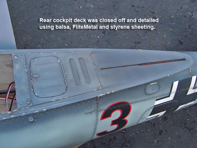
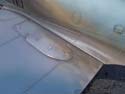
Rear cockpit deck
Now moving on, let's look at the cockpit deck area below the trailing "teardrop" section of the sliding canopy. While this area would normally be covered in the "Cockpit" section of this site, I had to get it laid up and painted during this phase of the build so I could blend it into the fuse and get clear coats over.
Basically I laid in some balsa sheeting in the rear deck area, blended it and began detailing. This area is constructed from balsa sheeting, some Cliental, and styrene plastic.
Once finished up, I painted it, weathered it and shot the clear coats over it while clearing the rest of the plane.
|
|
|
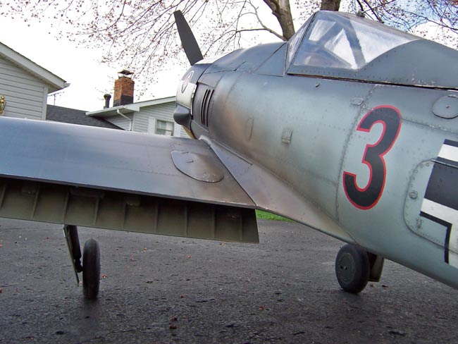
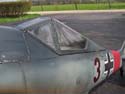
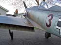
Decals and clear coats
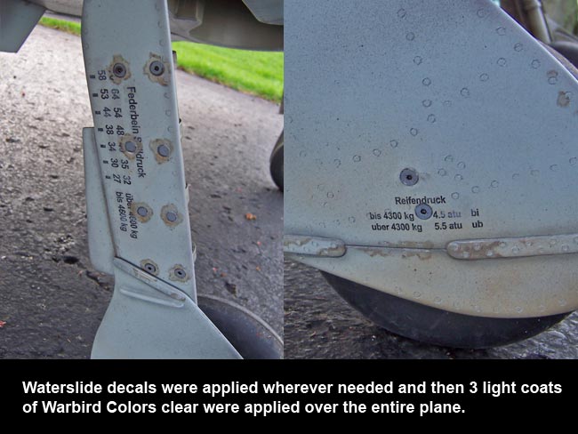
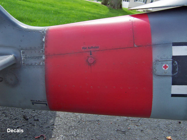
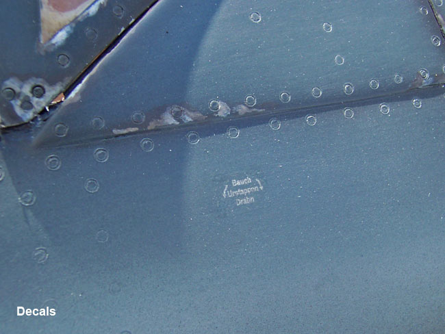
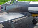
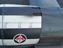
As usual, I applied all my scale decals onto the plane using custom produced water-slide decals that I drew up on my PC. Unfortunately I had to change vendors for the actual production of the slides, and I'm not overjoyed with these decals.
The transparent stock appears to be much thicker than that of my previous water-slide vendors. While this made them much less fragile to work with, the downside is that I found it very difficult to blend the edges of the clear decals into the fuse to my level of satisfaction. I believe that in the future I'll either use a different water-slide vendor, or switch to a dry-transfer decal vendor.
After wetting decals and sliding them off of their paper backing onto the plane, I allowed them to dry and set overnight. Then I made some efforts to better blend the decal edges away, but never really hit it the way I would have liked to. They don't look to bad, but I think they could have come out better.
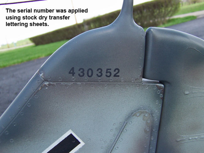
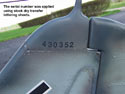
When it came to the large serial number printed across the top section of the vertical fin, I switched materials. For the S#'s I chose to purchase a sheet of stock dry-transfer lettering at my local craft store. This seemed to work a lot better and I didn't have to worry about blending in edges.
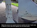
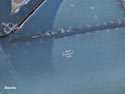
The pics at left show just a few of the many decals I applied to the airframe. Once the decals had all dried and set overnight, I added a little weathering over each decal, then shot 3 coats of Warbird Colors clear paint. I used the same HVLP gun and method as was used when shooting the color coats, except I had to increase the water dilution to nearly 50/50 mix.
The end result of the clear coats left the plane in a "semi-gloss" state Just a few light passes over the surface using a fine steel wool pad dulled it down a good bit to more of a satin finish. Make sure that when you do the steel wool steps, you take great care to LIGHTLY rub the wool over the plane surfaces in the direction of the scale wind flow.
|
|
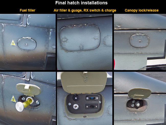
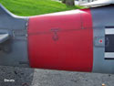
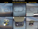
Operational hatches
This is a pretty straight-forward process. All the operational scale hinge doors were epoxied in place at this point. When doing this, make sure you don't get glue down in the hinges themselves.
I used a variety of means to secure the hatches in the closed position for flight. The fuel filler hatch was secured by affixing a small wooden block at the bottom edge of hatch door. This created a "pinching" effect which held the door shut in place when closed.
The door for the canopy locking lever hatch was pretty stiff, so I found that no special precautions were required to hold the door shut.
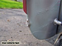
Lastly, the large door that covers the air filler valve & gauge and RX switch & charge jack tends to "want" to stay in the closed position, but I added a locking mechanism made from "Rare Earth Magnets.
|
|

|
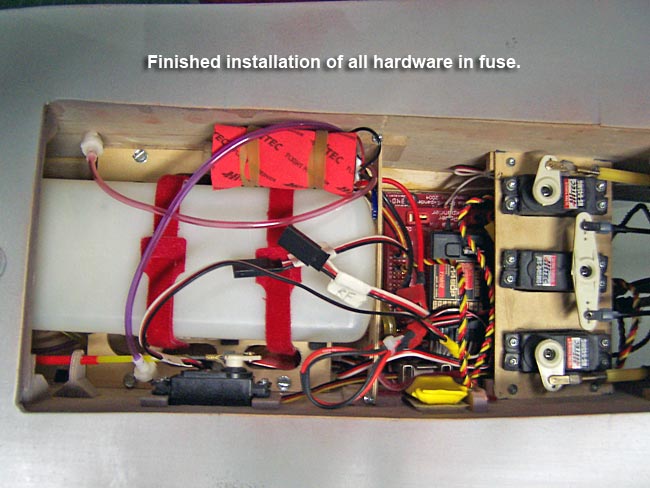
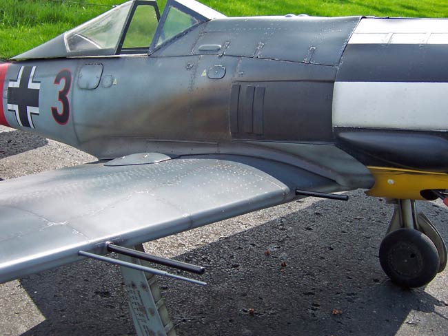
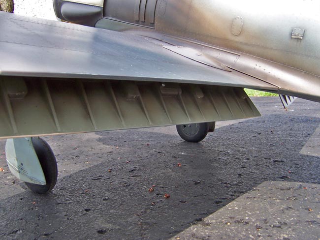
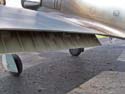
Gear installation
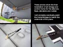
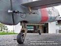
The first pic at top left here shows the final hardware, including servos, tanks, batteries, receiver, electrical and pneumatics, all being "crammed" crammed into the tight confines of the fuselage interior. I still need to better route some of these wires and hoses to make sure they stay out of trouble when the wing gets mounted.
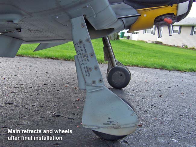
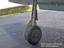
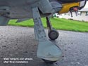
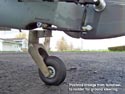
The next two pics show the Retract Main Gear after completing decals and clear coats. It took a while and a good bit of adjusting to get the final gear installation to line up at the proper angle, position, etc..
The linkage for all control surfaces was installed and tested for throws. The pics below show the hardware and methods used to secure the control surface installations. Wing servos were installed and leads were run through the channels using the dental floss that was buried inside the wing months ago during the build. I epoxied my custom-made control horns in place on all surfaces except the flaps. The flap horns were standard giant scale nylon horns with three 2-56 screws securing them to the horn blocks in the flaps. Nylon inserted lock nuts were used inside the flaps to secure the screws
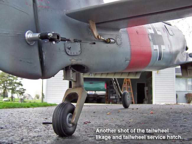
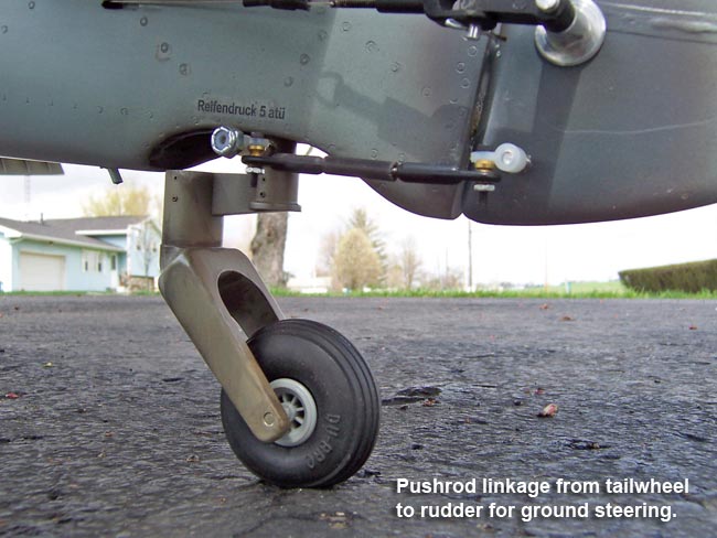
Note that I also installed the tail wheel steering push rod at this point. The push rod transfers the directional inputs from the rudder down to the actual tail wheel itself.
Eventually I plan to paint the linkages and control horns to match the underside of the FW190. This should help make them far less conspicuous.
|
|
Lights, prop & spinner
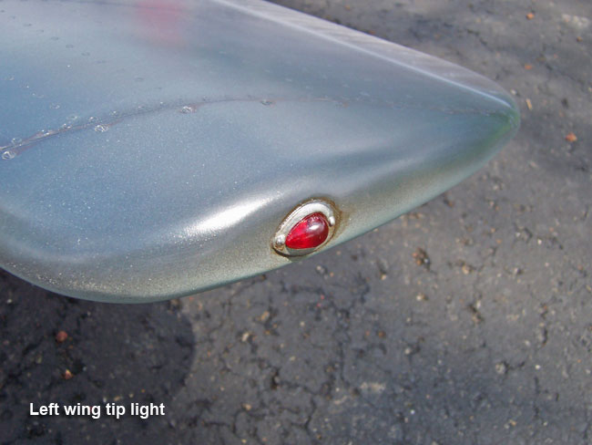
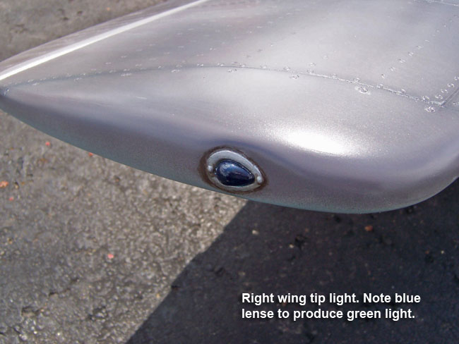
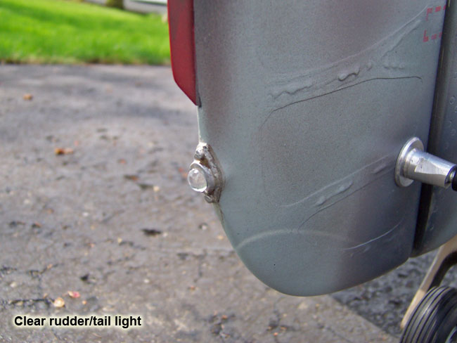
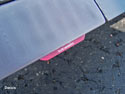
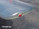
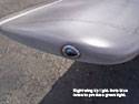
These three pics show the scale wing tip and rudder lights after installation.
The left wingtip is a red "bead" of sorts from a local craft store. The right wing tip light was made from the same thing. Note that while this light appears blue instead of green, understand that this was the case on all full scale planes as well. The yellowish bulb used inside these tips produced green light when shining through the blue lenses.
The clear tail light on the TE of the rudder was also constructed from a clear bead from the local craft store.
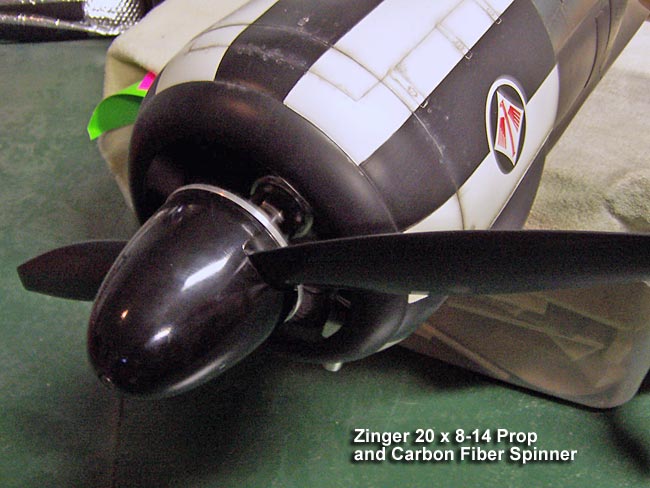
 Lastly, I drilled my Zinger 20 x 8-14 prop, cut my carbon fiber spinner and assembled it all together after balancing the prop. I had to order some special bolts to secure the spinner to the prop bolt. I used a 10-32 socket head screw at about 3-1/2 to 4 inches long to secure the spinner to the prop bolt. Lastly, I drilled my Zinger 20 x 8-14 prop, cut my carbon fiber spinner and assembled it all together after balancing the prop. I had to order some special bolts to secure the spinner to the prop bolt. I used a 10-32 socket head screw at about 3-1/2 to 4 inches long to secure the spinner to the prop bolt.
|
|
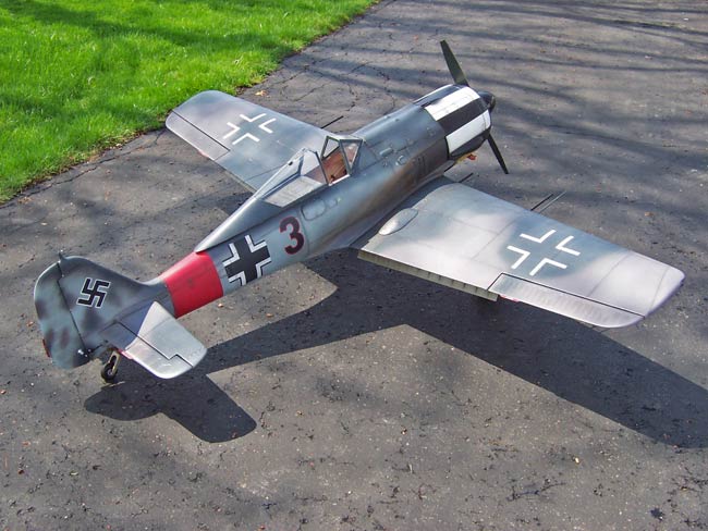
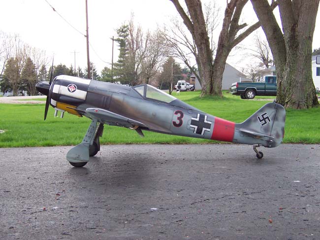
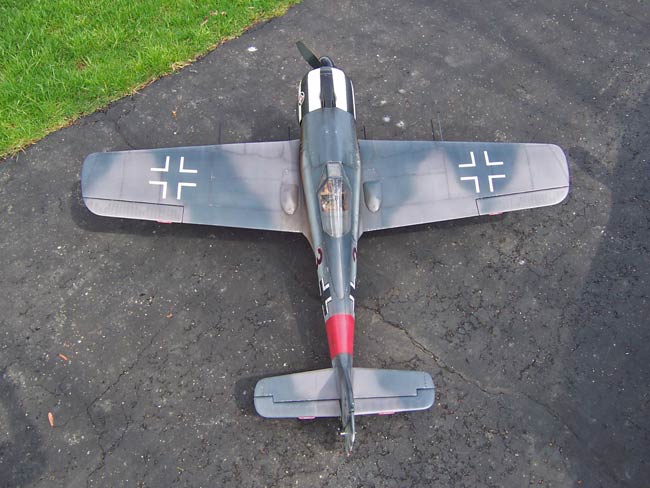
Gallery
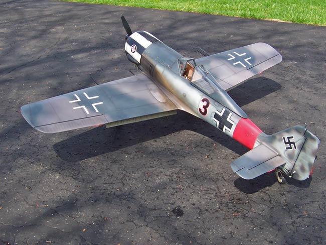
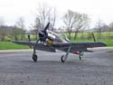
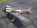
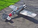
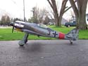
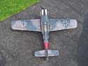
Well, I hate to post this "gallery " of pics at this point because the project is really not finished yet. I still have to work out a few wire & hose routing issues in sided the plane, get it balanced and finish the cockpit interior.
This time around, I plan to stop here and wait until I get the plane flying before attacking the cockpit. I prefer not to spend the time and money to deck out the scale cockpit until after I have flown it as is and found everything to check out. I don't want to waste this effort only to find the plane to not fly and perform to my satisfaction.
Once I have a few successful flights on this plane, I'll jump back in and build up the scale cockpit, and possibly pilot figure. I have to be cautious of adding too much weight to the airframe since the cockpit is far behind the balance pont. If I add 4-5 ounces in cockpit detail, it would mean adding the same amount of ballast weight to the nose to offset the balance issue. So, 4 ounces added behind CG means 4 ounces need to be added in front of CG... translating to 8 ounces.
If I find the plane to fly too heavy, I may skip the cockpit. If I find it to find light enough, then I'm more likely to go ahead and add the cockpit interior. So far I think it's looking pretty good, and the AUW is 24 pounds RTF, without ballast. Hopefully it won't take too much lead to balance. I hope to come in well under 25 pounds, even with the cockpit and ballast.
Next up, it's now time to start our flying season here in Ohio and I need to knock the dust of my transmitter and my knuckles. The 190 will get put aside a while until I'm ready to take it up. If all goes well, I'll begin populating the "Cockpit" section of this site soon. |
|
|
|

|
|