Constructing the Tailgear and Control Linkage
This was one the trickiest parts of the whole project... so far. While I actually did this step prooSince Jig Dog's plane was based on the carrier Enterprise, it probably used the standard carrier style tailgear setup most of the time. The SBD crews changed this around from time to time, removing the fairing, changing wheel styles out, etc., but the standard setup was the "coaster style" tailwheel with a removable fairing that covered the tailgear suspension.
Again, this step was actually done earlier, prior to planking the bottom of the fuse, but I wanted to move all the tailgear stuff to a separate page.
|
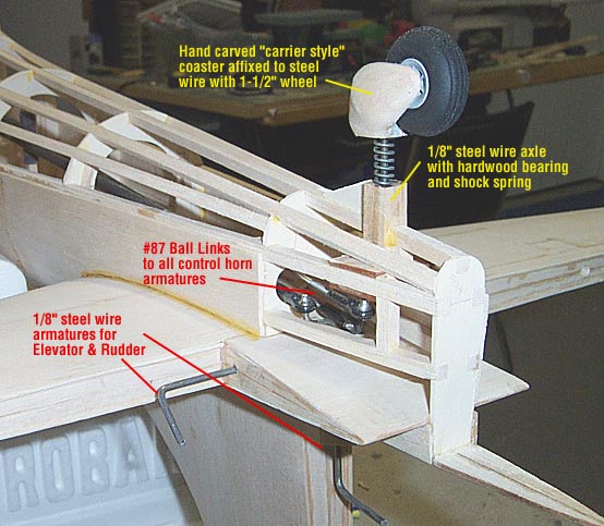
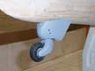
Since I fly off a grass field, and also because I don't know of a scale wheel that matches the small solid rubber wheel used on carriers, I chose to use a standard treaded 1-1/2" tire. I built the coaster facsimile out of solid balsa glued to the 1/8" steel music wire that I bent earlier and ran through a hardwood bearing up into the fuse. This wire has a spring over it and a soldered washer on it to form a "shock absorber" for the tailgear.
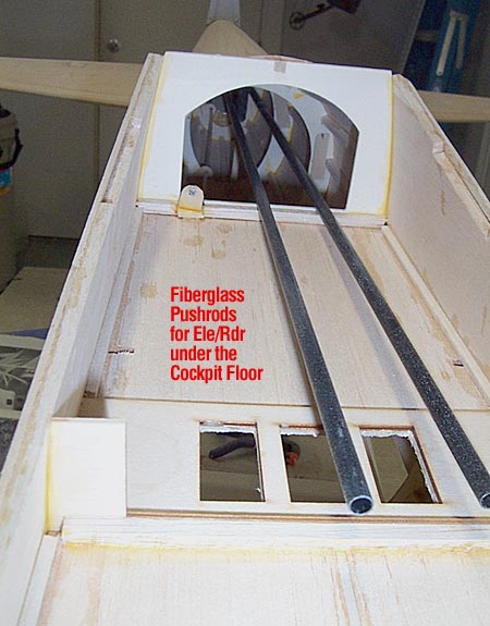
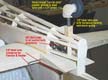
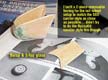
Once the gear was all in place, including the steel wire that for the rudder and elevator, I went ahead and snapped the nylon bearings onto the ball links. I threaded 4-40 rod into each of the ball links and glued the rods into two Dave Brown fiberglass pushrods. One rod is linked to the ball link on the elevator control horn, and the other rod controls both the rudder and tailwheel.
|
To do this, you have to run two 4-40 rods out of the fiberglass pushrod, with one running to the rudder control horn ball link, and the second to the tailgear ball link. You have to take special care here to perfectly align the tailwheel to the rudder in this step so that they are synch'ed up properly. Moving this pushrod now turns both the rudder and the tailwheel.
|
ALERT!
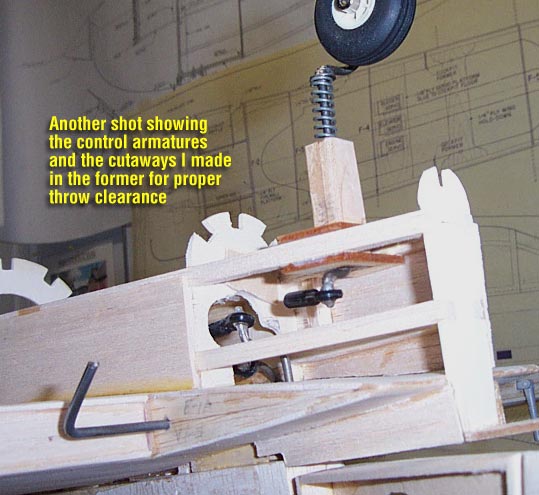
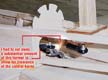
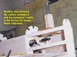
I feel that I found a serious flaw in the plans regarding this area of the construction. Even making sure that I bent my music wire exactly as shown on the plans, there is absolutely no way that there will be any clearance from the nearest forme to let the control horns swing with clearance.
I ended up using a dremel to grind away about half of the former and even a bit of the stringers so that the wire horns had clearance. so much of the former was removed that I added a good bit of balsa and light ply in this area to regain structural integrity. After doing this, everything seems to work just fine.
This issue was corrected and completely redesigned in the latest version of the Bates plans and is designed for pull-pull linkage now.
|
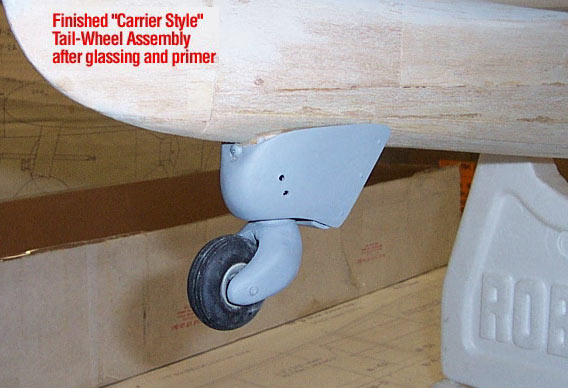
Making the Tailgear Fairing
|
The SBD had a few variations of a removable fairing over the tailgear suspension. I wanted to make mine removable as well, so I could get back into this area, and also since I anticipate it may take some abuse and may need repaired or replaced at some point.
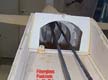
I made the entire apparatus out of varying thicknesses of balsa sheeting, cutting pieces to different shapes, bending them and gluing them until I came as close as possible to the proper shape. I added a little extra solid balsa and putty to the back end to get the rounded shape.
I used 2oz fiberglass cloth on the inside of the fairing and 3/4oz cloth on the outside to form a strong but light composite fairing. I have three small screws that I use to mount the finished fairing to the fuselage.
|

"Moving on the business end!"
|