|
The Starboard Side Pilot's Wall
|
This section covers the fabrication of the entire starboard side of the pilot's section of the cockpit/interior. More of the same styrene, balsa and FliteMetal fabrication techniques will be shown here. I did come across a few additional new techniques and tips that I will cover here as well. Here's one tip...
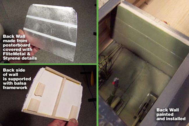
Many of you may know this, but "tailoring pins" can be picked up at any fabric store and turned into some pretty cool "levers" for your cockpit. The pins can be used as is or you can add more scale stems from styrene.
|
|
|
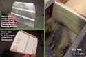
First, the Back Wall
OK, first I've got to get the "back" wall out of the way. It's pretty simple, so here's the one tip I'll give you on this section that I used from here on out.
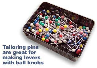
To build the large wall sections, I actually found "posterboard" to be a great material. I built the wall out of posterboard covered with FliteMetal and supported the backside of it with balsa framework. Styrene details were also added. Here's the advantage of posterboard for large interior panels...
- Cheaper than styrene
- Flexes and bends easier
- Is not brittle like styrene
- Easier to cut and work with
- Just as light even with FliteMetal applied
|
|
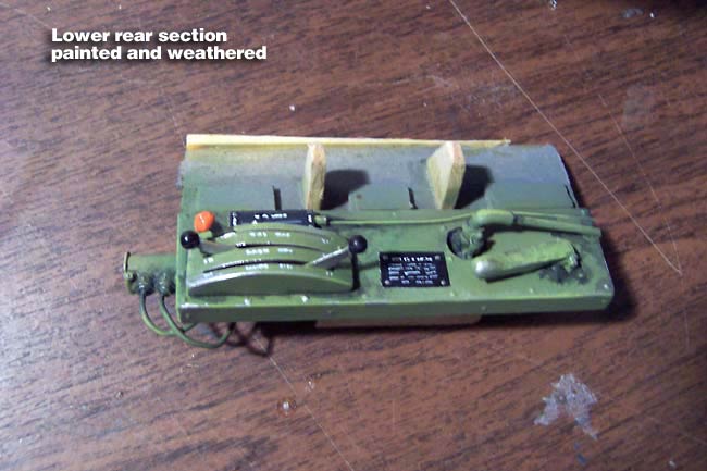
Lower Rear section of Starboard Wall
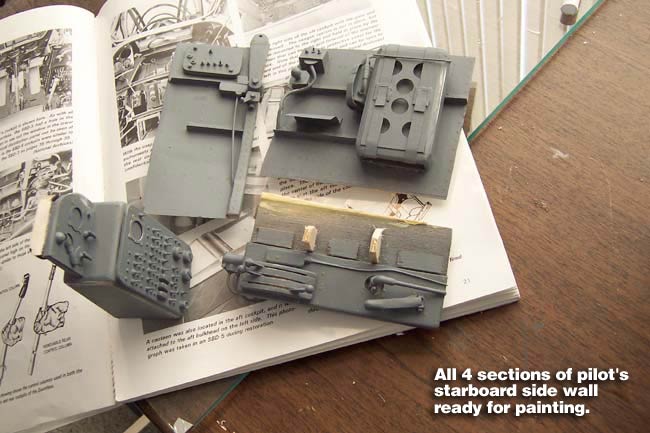
Moving on to the starboard wall, I broke it up into 4 sections. The first section is the lower rear section, which is basically a "shelf" that sticks out of the wall. I didn't build the wall underneath this shelf, since it is not visible. This was built from balsa and styrene and I used the tailoring pins to make the lever controls for the flaps and dive brakes.
|
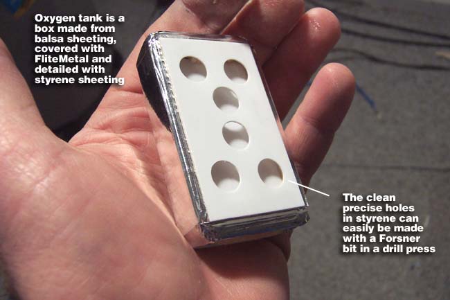
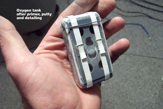
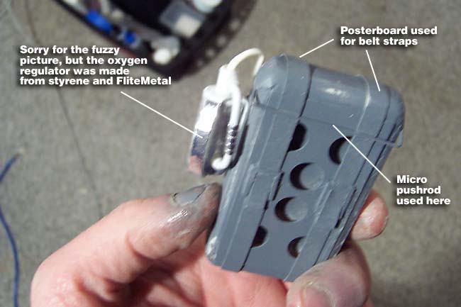
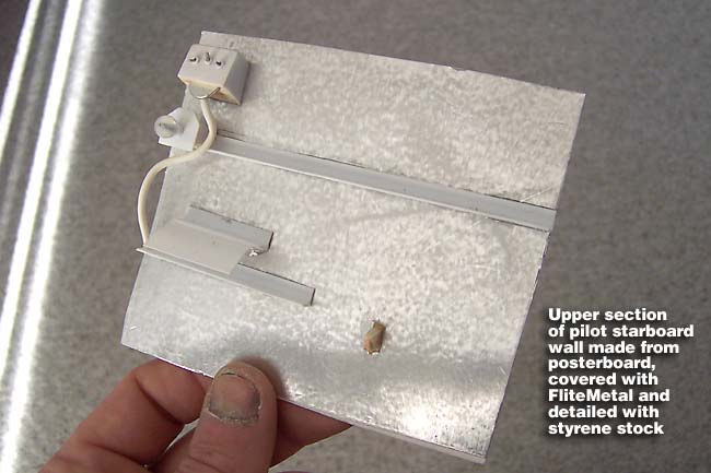
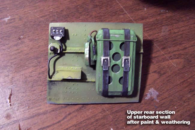
Upper Rear section of Starboard Wall
Here's the upper rear section. I built this wall out of posterboard and FliteMetal as well. The major detail on this section was the oxygen tank and regulator. This was built from balsa, styrene, FliteMetal, posterboard and a piece of micro pushrod.
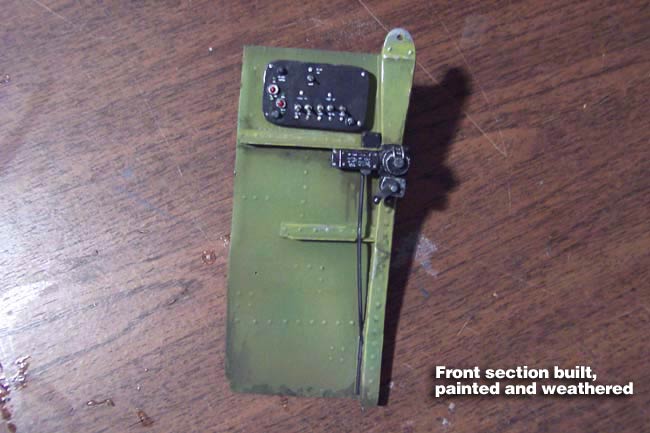
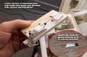
Forward section of Starboard Wall
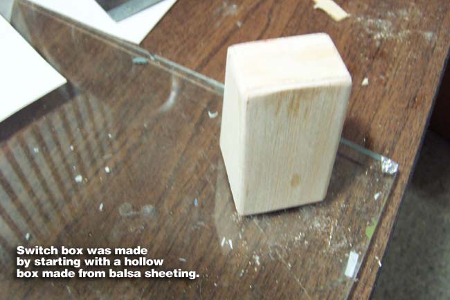
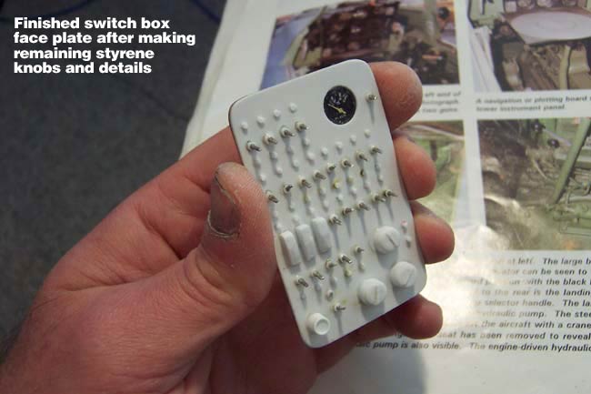
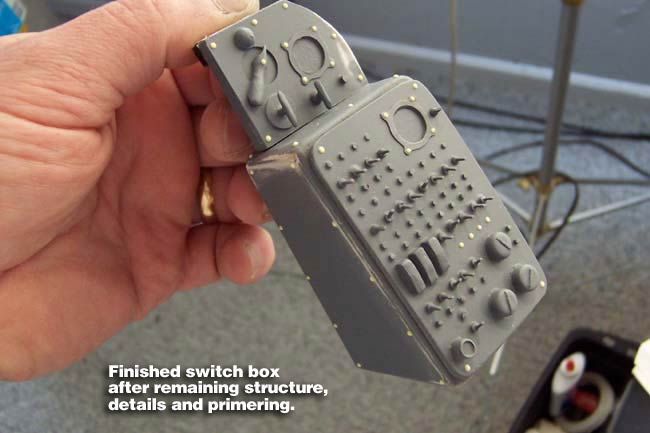
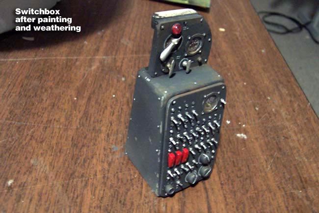
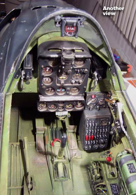
The forward section was built in 2 separate components, the wall and the "switch box." The wall section was constructed using the same techniques as the other sections. The switch box was built as a hollow box made from balsa sheeting. The face plate was a 3-ply laminate made from 1/32" aircraft ply, clear styrene and white styrene.
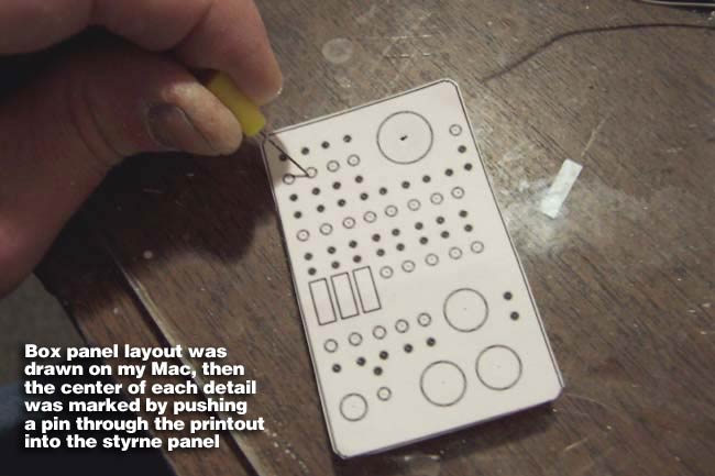
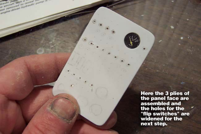
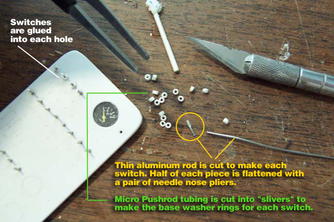
This used the same basic technique as the main pilot instrument panel, but all was cut by hand instead of laser cutting. The switches were made from aluminum rod that is flattened at one end with pliers. Base nuts for each switch were made from slivers of micro pushrod tubing. All other details were styrene stock, including the 2 hand-cut instrument bezels.
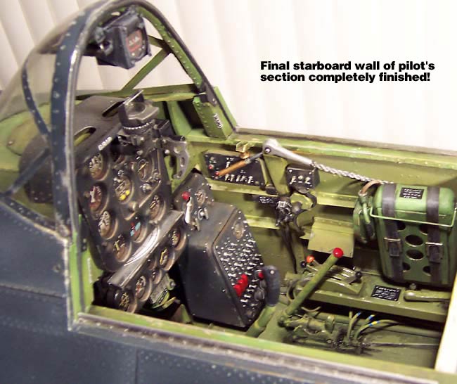
Painting, Weathering and Installation
Here are all 4 components after painting and weathering with hobby acrylics...
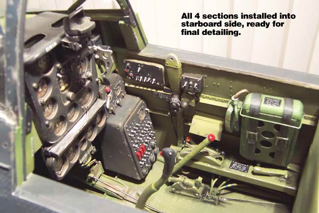
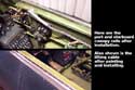
Here all 4 components after gluing them in place on the starboard side...

 |
Additional Detailing
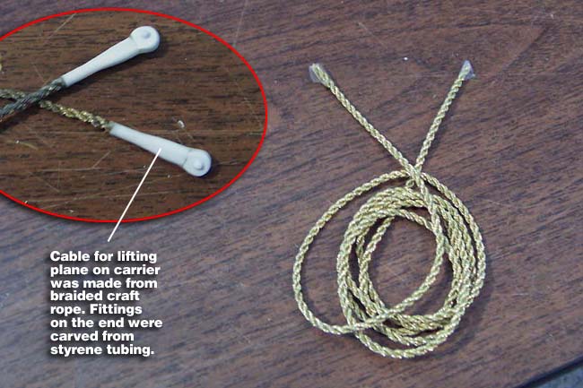
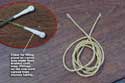
The SBD has a large cable that is connected to each side of the cockpit, which is used to lift the plane with a crane when needed and for hanging the plane from the ceiling inside the carrier. This was to overcome the lack of folding wings on the SBD and obtain more real estate for planes.
I made this cable from a piece of thin braided rope/string I picked up at a Fabric Store. The fittings on the ends were carved from styrene tubing, and all was painted silver and weathered.
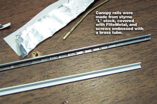
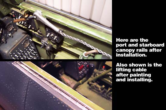
To make the rails for the pilot's sliding canopy, I used styrene "L" channel and covered it with FliteMetal. I used a 1/16" brass tube to burnish/emboss screw heads into the FM material. After a wash with thinned black acrylic, the FM was wiped down to reveal the detail.
|
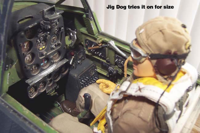
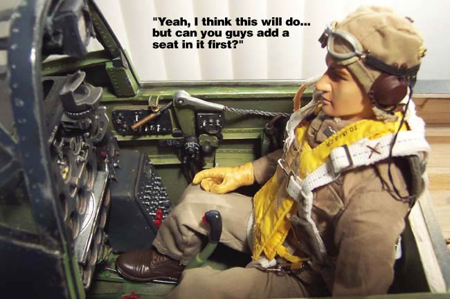
All Finished and ready for Jig Dog's Inspection

"Port Side of Pilot Section"
|