Finishing the Landing Gear
I started out my landing gear by first running through the installation of custom Robart pneumatic retracts with Dubro LiteTread 5" Tires. This was covered back in the retract install section. Taking this to the next "scale" level requires additional detailing of both the retract struts and the wheels. I put as much accurate scale detail as possible into these components, but had to walk a fine line between scale accuracy and RC functionality.
This meant that some of the scale geometry had to be altered to make the doors function and also to avoid any "high-risk" potential for inhibiting the gear from operating properly. This is often unavoidable when doing a flying, functional RC model, so you do what you can to make it look "believable" but still maintain the integrity of all functional components.
|
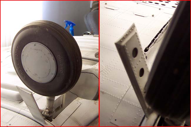
Hinging the Operational Strut Doors
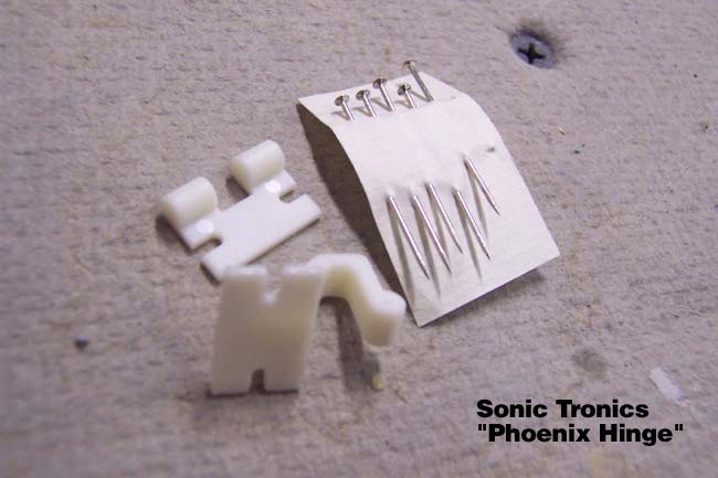
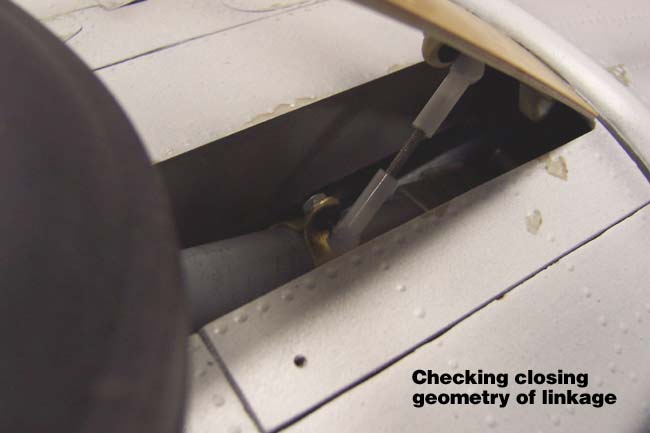
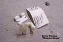
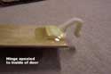
The fullscale SBD had a different relationship between the gear pivot point and door pivot point than that of the RC model. For this reason, the geometry of the "door swing" has to be different than the fullscale. Also, the shock travel of the model struts is proportionately greater than that of the fullscale struts, requiring more clearance from the door linkage. For this reason, I had to go with the offset "Phoenix Hinge" from Sonic Tronics.
This hinge comes in 2 pieces with a set of pins for the hinge points. This entire hinging process required a lot of trial and error to find just the right geometry that would best perform the task at hand. I did this by tack gluing the components into position, testing and repositioning as needed. I had a big help in the form of a photo that Phil Clark over in the UK had provided me. He used the same hinges on his Bates 85" SBD/A24, so I got a good idea of where to start positioning things at.
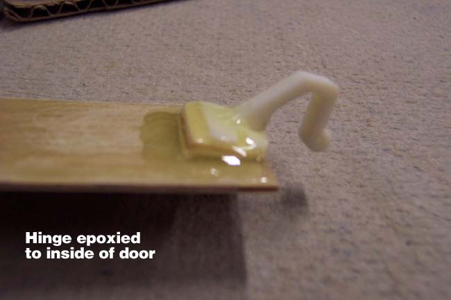
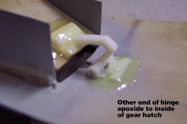
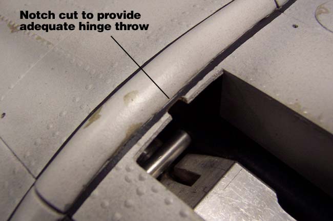
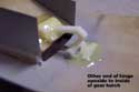
Once I was relatively confindent with my positions, I then epoxied the long half of the hinge to the underside of the door, and the short half to the underside of the gear access hatch. With the pin in place I began working on getting my hinges to clear the access hatch and wing joint bead. To do this, I had to notch a spot in the access hatch and file down a bit of the outer hinge half. Otherwise, the hinge would bind on the hatch and/or wing joint bead.
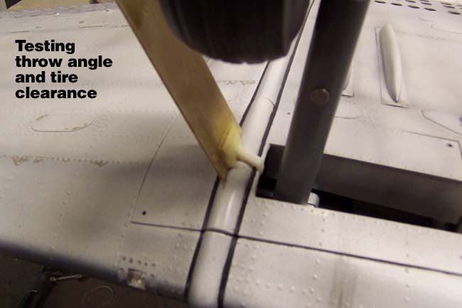
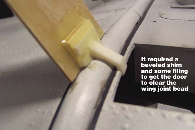
The next obstacle was to get the door to swing wide enough to clear the tire, and through the full range of shock compression in the struts. This meant I had to angle the doors out further (like the fullscale) than what the wing bead would allow. To overcome this, I had to put a small ply shim between the longer/outer hinge half and the gear door. This set the door at a wider angle when the hinge was fully opened.
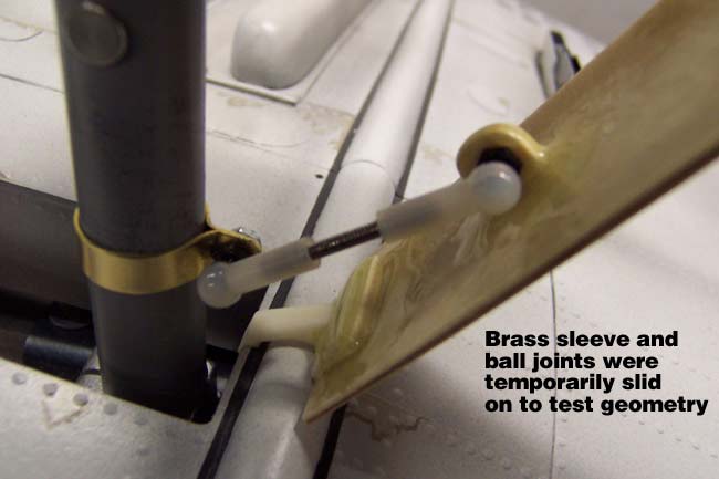
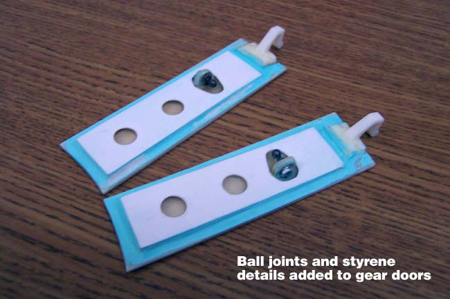
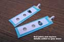
With the door hinges functioning pretty well I had to then work on getting the proper position for the strut band and door linkage. I used small 256 ball joints on both the door and the strut and connected them with a short link of threaded 256 rod. The strut ball joint was attached to a 1/4" x .025" brass strap and the door ball joint was attached to a small tab made from 1/8" ply.
Sliding these 2 connection points up and down until I got the optimum geometry took a little patience but wasn't that difficult. I would have preferred to position them both closer to the wheel, but again, the wheel travel required for the strut shocks dictated their relative position to the tire. This is one of the "scale innaccuracies" that I mentioned earlier, but it's totally unavoidable if you don't want your gear to compress on landing and smash into your door linkage.
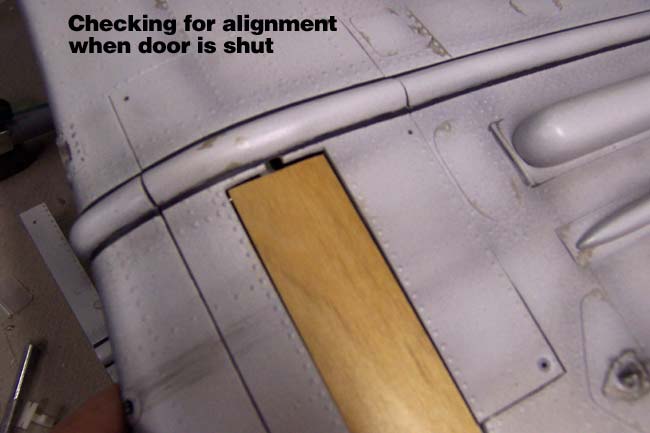
With the linkage pretty much worked out, I did my final epoxying and ran the doors through range of motion tests to make sure the doors sealed when the gear closed and swung out properly, without binding when the gear locked into the "down" position. The nylon ball joint connectors make it easy to fine tune the length of the rods to get the open and close positions just right.
|
 |
Detailing the Strut Doors
The gear doors were formed earlier by cutting them out of the gear access hatches. You can see this process here. But now that the hinges and ball joints are on them, I can proceed with detailing and painting. I began by cutting the raised inner door panels out of styrene sheeting, drilled the scale lightening holes in them and relieved an area for the ball joints.
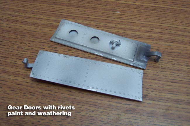
I raised them up off the door with a thin balsa shim around the perimiter. Once glued on, I then blended the panel down onto the door using Acryl-Green Spot Putty. Once dry and sanded, I primered and added all the scale rivets. Next comes the latex paint, weathering and finally the clearcoating. I had to take great care in painting and weathering them as they had to match and blend in with the paint & weathering on the bottom of the wing & access hatch. No big deal, just pay attention.
|
 |
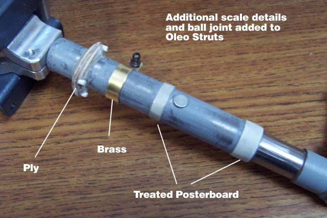
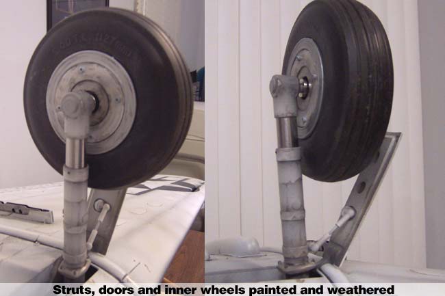
Detailing the Oleo Struts
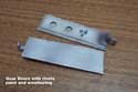
As I mentioned earlier, I used a 1/4" brass strap to connect the linkage ball joint to, so that took care of one detail. In addition to that, I made more scale relief details using my own method of treating posterboard. I glued strips of posterboard around the struts, then soaked them with thin CA to harden them and smooth the surface. Next I hit them with a coat of the Minwax PolyCrylic that I glassed the plane with. Once primered, they looked just as real as the metal parts.
For the large rectangular ring at the top end of the strut, I cut and shaped a piece of 1/4" plywood, split it in half lengthwise, and glued the 2 halves back together around the strut. I added bolts made from styrene hex rod.
|
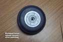 |
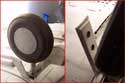
Detailing the Inner Wheels
I detailed the Dubro 5" LiteTread nylon wheels to look as scale accurate as possible but had to make a little concession in detail to avoid flimsy details that would break or snag in day-to-day function of the retracts and landings.
To detail the inner/brake side, I cut a couple rings of relief from styrene sheeting and left a hole for the inner wheel collar. I cut these small enough to rest just inside the outer releif ring that's already molded into the nylon wheels. This gave me a nice outer ring to simulate the metal brake rotor and a painted white inner wheel with a little stepped relief. I screwed these into place using 256 screws, so they are snug, but removable. The styrene portion was painted white, weathered and clear coated.
|
|
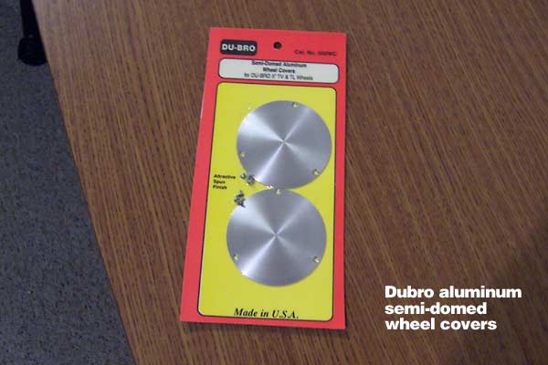
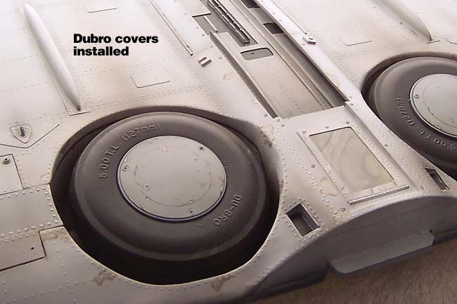
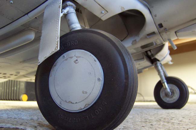
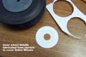
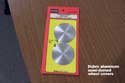
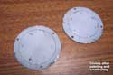
The Outer Wheel Covers
For the outside of the wheels, I purchased aluminum semi-domed scale wheel covers from Dubro, specifically made for the Dubro wheels. Although they look great and are very scale accurate, they have unfortunately been discontinued by Dubro. Like me, you might get lucky enough to pick up one of the last few remaining on distributor shelves!
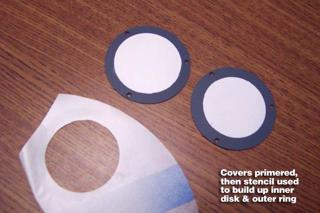
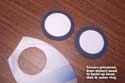
I first primered them with a lacquer etching primer for best adhesion to the aluminum. Next I cut a frisket stencil to shoot standard lacquer primer through, building relief to show separation between the inner dome and the outer ring (like doing primered panel lines).
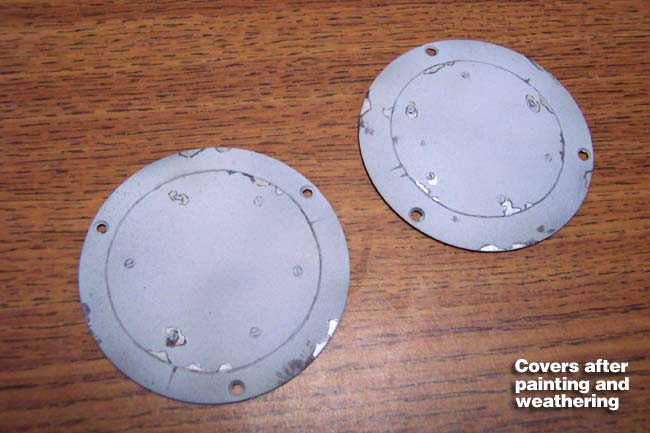
After drying, they got the usual latex paint, acrylic weathering, and Nelson's clearcoat. Before the clearcoat though, I did use a brass tube to twist the 6 scale screw heads into the paint on each cover.
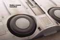 After an overnight cure, I drilled the holes in the nylon Dubro wheels and screwed the 3 supplied screws into each wheel to secure the domed covers. I'm a little leary about using just 3 very tiny screws here, and may explore additional options. I've thought about adding a dab of epoxy to the back of the covers, or gluing a rare earth magnet to the back that will grab to the axle & wheel collar. After an overnight cure, I drilled the holes in the nylon Dubro wheels and screwed the 3 supplied screws into each wheel to secure the domed covers. I'm a little leary about using just 3 very tiny screws here, and may explore additional options. I've thought about adding a dab of epoxy to the back of the covers, or gluing a rare earth magnet to the back that will grab to the axle & wheel collar.
|
|
Final Assembly & Testing
With all components fabricated, test-fitted, painted and complete... I'm finally ready to assemble. All the retract airlines were permanently routed and connected, then the retracts were bolted in and LocTite applied. All my wheel collars got the LocTite treatment and they were locked down along with the tires. The gear access hatches were mounted and held in with five 256 screws each.
The ball joints were tightened with LocTite on the screws and all connected to the rods. On the ball joint for the strut, I ran a strip of white graphic arts tape under the brass band to act like a gasket. This compressed giving the band a snug fit without slippage and also reduced the potential for RF noise. I also added a couple drops of thin CA into the joint where the band wraps around the tape and strut.
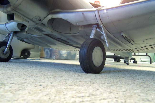
With the fuse mounted, air tank pumped up and radio on, I ran the retracts through their paces ensuring good clean range of motion, proper start and stop positioning of the doors and plenty of power through multiple cyclings of the gear. Everything passed seems to work fine so far!
|
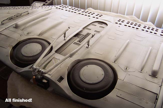
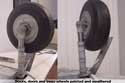
That's it, gear all detailed and installed. I would have liked to add more brake lines and details, but I just did not feel comfortable with them risking the operations of the retracts. I was too concerned with small pieces breaking under landing stress and/or brake lines coming loose and getting snagged by the wheels or access hatch. It's just not worth losing the plane over to get those last tiny details.
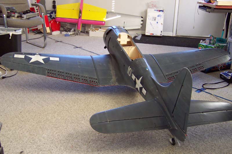
Here's a few new pics with her standing on her own 3 feet for the first time...
wish I had put the trapeze on for these pics. ;-)

"50 Cal Nose Guns"
|