Hinging the Control Surfaces

I know that hinging control surfaces isn't really part of "Paint & Detail" but I'm putting it here in this section because it's best to do this step after painting & clearcoating. I'm trying to keep my progress in chronological order, so here you are. At any rate, this page covers the steps I took to do my final hinging of all 10 control surfaces.

This process, like glassing and painting has a number of techniques and material options available, and is very controversial as to which is best. I'm not going to debate those points here, most are all valid options. Since this is my first time doing anything but CA hinges on a "kit" I wanted to stick to the Jerry Bates plan and design in regards to hinging.


Flaps & Dive Brakes

As outlined in the Construction section of this site, I used Nelson metal piano hinges to hinge my 2 Dive Brakes and 3 Flaps. See that section for more details. My first step here was to epoxy the piano hinges of the 5 surfaces to the trailing edges of the wing. I had already used a few screws to set the alignment when originally installing them, so position wasn't an issue. I added more screws before the epoxy set, spacing them about every 2-3 inches to "pin" the hinges and make the joint stronger.

After doing each surface one at a time, and letting the epoxy cure over night, I then painted the trailing edges and hinges white, weathered them and added Nelson's clear. A ran the five servos (one on each surface) through their paces and set all my throws and trims. The servos are Hitec HS475HB resin gear servos with 70oz of torque at 6 volts.

I have all surfaces set to about 40-45 degree max throws. For now, the flaps are set to a variable rate dial, but I may change that to a 3-position switch later. The brakes are set to a switch and slave the flaps to go to 100% when brakes are deployed. All control linkages are completely hidden and only the control horns can be seen when flaps and brakes are fully opened.


Ailerons

Many guys would opt to do Frise ailerons and other advanced scale hinging options, but I chose to minimize my re-engineering. Check here to see my construction. I used the flat nylon Klett "pinned style" hinges, putting 3 in each aileron per plans. I began by cleaning the hinges with alcohol and lightly scuffing them with fine sandpaper. I then epoxied them into each of the ailerons, with the hinge pin positioned just outsed the front of the aileron. Before the epoxy fully cured, I mounted them to the wing to test the alignment and bend the hinges back and forth as it cured.

Once the epoxy was set, I then epoxied the other end of the hinges into the wing, again flexing the hinges as the glue cured to ensure full range of motion. I hooked up the 4-40 rods & clevises to the control horns and servos and tested all operation.

I used Hitec HS645MG servos on each aileron, with 133oz torque at 6 volts. I set my control throws to 3/4" up & down on low rates and 1" up & down on high rates. The ailerons have the only visible control linkages on the plane, but the unobtrusive control horns and servo arms barely stick out of the plane on the underside. I would prefer to have had the more scale Frise style ailerons and hinging, but that will have to wait for my next project!


Elevator & Rudder

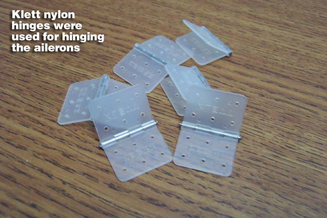
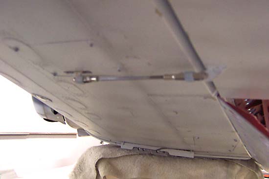
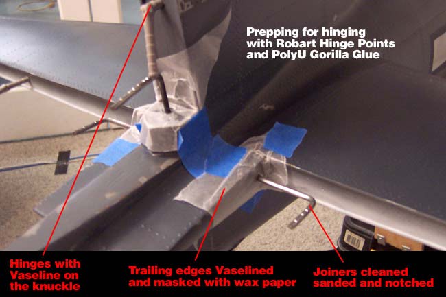
The Bates SBD design uses completely hidden/internal control linkages for the tailfeathers, check here to see the construction and here to see how it ties into the tailwheel. The linkage utilize 1/8" steel wire joiners into the surfaces, which double as an additional hinging point. In addition to these hinge points, each of the 3 surfaces get 2 of the large Robart hinge points. These were glued in with a waterbase PolyUrethane glue called "Gorilla Glue."

Before hinging, I began by prepping the tail for the hinging and gluing steps. To do this I used Vaseline to lube & protect/seal the hinging "knuckles" of each hinge. I used a toothpic to pack the Vaseline into each knuckle, which will help keep excess glue from getting in there. Next I cleaned the metal joiner wires with alcohol, sanded them, and then used a file to "notch" them providing "barbs" like the Robart hinges. This helps give the glue something to lock onto. I then packed a little Vaseline into the holes where the metal rods enter the tail, and also put a small piece of wax paper over the entire area where these rods sleeve into the tail to keep glue from getting in there.

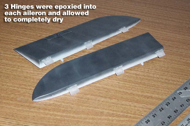
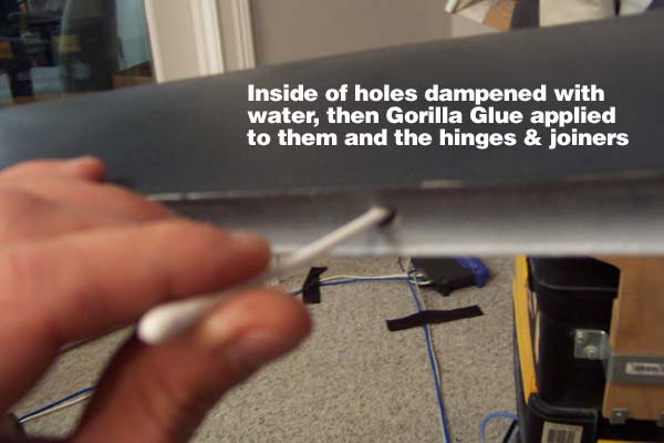
Now, working on one surface at a time, I glued them on using the following steps. I first use a toothpick, shishkabob skewer, or Q-tip with the cotton removed to apply a little water to the inside of all the hinge holes. Just slightly dampen the surface, as the moisture is what "kicks" the Gorilla Glue. Next I use the same technique to apply a light coating of the Gorilla Glue to the inside of the holes, onto the metal joiner wire, and on one side/half of the Robart hinges. Next I inserted the hinges into the trailing edge of the surfaces about half way. Wipe the excess glue off that oozes out, then push them the rest of the way in and wipe again.

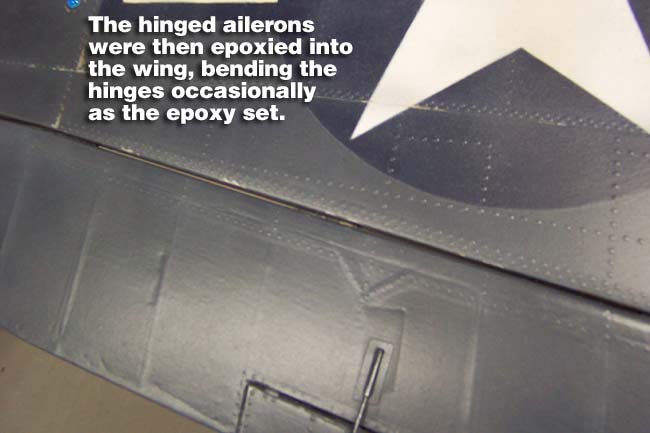
Now apply the Gorilla glue to the other half of the Robart hinge that's hanging out, and slide the control surface on. Again, wipe off the glue as it oozes out. Flex the surfaces back and forth to check the alignment of the fulcrom/knuckle. By now the glue will start "kicking" and begin to foam.

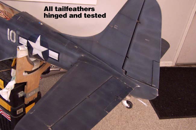
This type of glue will expand to 3-4 times it's volume as it cures, expanding into every nook and cranny and wrapping around the hinge barbs. It is also going to want to expand all over your hinge knuckle, which is why you use the Vaseline, but you still need to keep wiping everything off for about 1/2 hour as it continues to expand. Every few minutes you flex the hinges and recheck alignment. You can also use a toothpick to pick the foaming glue out of tight spots, hinges, etc. After about an hour, the glue is pretty much done and set, but won't fully harden/cure for about a day.

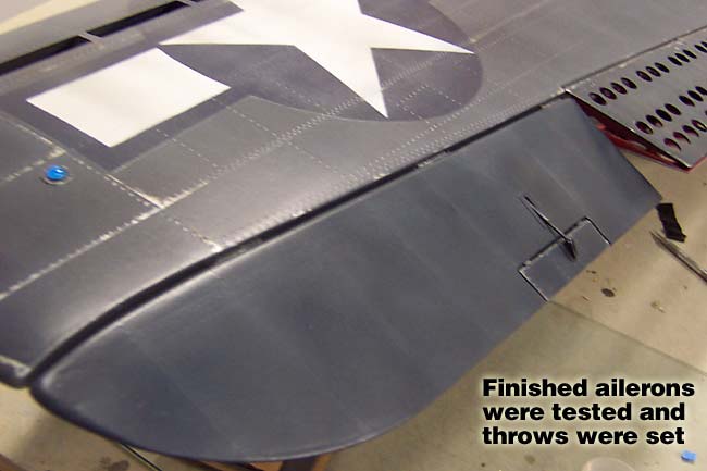
Now you go ahead and hook up servos, set throws and you're all done. I used one HS645MG on the rudder and one on the elevator. I set the elevator to 1" up & down on low rates and 1-1/4" on high rates for now.

Well, that's about it. There are a lot of different ways to do this step but I've seen all the above materials and techniques used successfully a number of times and it's pretty much the way the Bates plans tell you to do it. In the future I may modify my hinging on projects to make them even more scale accurate, but I think this turned out just fine for my first crack at a scale warbird.


"Finishing the Landing Gear"