Adding a Dummy Radial
 |
Knowing that I'd need nose weight in this plane anyway, and that I wanted the most realistic yet durable radial dummy I could get, I went with the Frank Tiano resin dummy. It's very close to a scale replica of the engine in the SBD and was relatively affordable at $28. I was told that this dummy is molded from a polyester resin & microballoon composite, although it cuts and drills as though it has some milled fiberglass in it? The weight of this dummy "out of the box" is 12 ounces... I know that's heavy, but it's useable nose weight instead of dead lead.
|
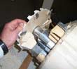
I began by measuring my cowl and cutting down the outside/perimiter of the dummy until it fit well within my cowl. Next, I used a Dremel to grind out the backside somewhat, effectively "hollowing it out" more to reduce weight (may end up wishing I left the weight in there!). Also, I had to cut out an area to allow for the electronic ignition timing sensor on the prop shaft. Once I had it whittled down to the final size and shape, I cut a 1/16" aircraft ply backplate to help stabilize it and provide a mounting surface.
With the backplate cut to size, I cut out areas between the cylinders for airflow. Note that I left most of the top half of the backplate solid to restrict the inlet air to the bottom half of the radial. This pushes the air across the cylinder and muffler, not up into the open/empty area of the cowl. It also helps to keep the 1:2 ratio of inlet to outlet air. You need to have twice as much air exiting the cowl as you do entering the cowl to properly provide cooling. With the backplate finished, I epoxied it to the back of the resin dummy.
Making a removable mount configuration

|
Next I had to sightly widen and recenter the prop shaft hole... it was drilled/molded a little off-center from the "factory". I then mounted it over my prop shaft testing the fit and clearance, and shimmed it dead center on the shaft using balsa shims. Then I mounted the cowl and "tack-glued" it to the dummy with CA. I could then remove the cowl with the dummy temporarily mounted to the cowl in correct position.
| With the dummy in place, I marked the inside of the cowl about where the back edge of the dummy was. This was to be my starting position to align my plywood mounting blocks that were to be glued to the inside of the glass cowl. This should have put me dead nuts on, but unfortunately I later found that I had to tweak this a little with some plywood shims. |
|
|
With the positions marked, I sanded some ply mounting blocks to shape, pre-drilled them and epoxied them into the cowl. Next, I test the fit, shimmed accordingly, and made some metal mounting tabs. I then epoxied the metal mounting tabs to the backplate of the dummy and screwed the assembly together. Lastly, I mounted the cowl and dummy combination onto the plane and found everything to be very solid and aligned very well. The slight apparently misalignment of some of the cylinders was due to some problems with the Tiano mold. I found that the resin dummy was a little "warped" right out of the box, and the 9 cylinders were not all exactly alike in size, thickness, etc..
Making lifter arms

|
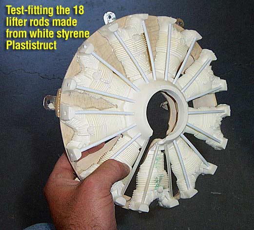
Now I needed to get set up for the scale lifter arms/tubes. I made them out of white Plastistruct 1/8" styrene rods (only had enough for 15, so I made 3 out of nyrod tubing). After cutting them to length, I drilled holes into the resin dummy to allow me to slide them through the top of the cylinder heads and down into the radial dome around the prop shaft. There are dimples in the dome mold that show you where the rods should be drilled into. After test fitting them all, I removed them to later be glued in place after painting the dummy. |
|
Making an air baffling system

|
To properly cool a gas engine, you need to make sure that you get adequate airflow in the right places. The rule of thumb is to provide twice as much exit airflow area as you have coming in (inlet airflow). With a giant 8 inch circular opening in a radial cowl, there's no way you can do this without reducing the inflow of air significantly. This is why I covered most of the top half of my dummy radial with the light ply backplate and left openings between the cylinder heads in the bottom half.
Taking this one step further, I chose to construct a light ply air baffling system on the backplate that would direct the incoming air to the exact places I wanted it to go (over the cylinder head and muffler) and away from the places I didn't want it to go (across the carburetor velocity stack/venturi. This method should give me a high rate of airflow across the hot spots of the engine and eliminate any venturi effect sucking air/gas out of my carb.
|
Painting, weathering and distressing
| Before I could even consider painting this dummy, I had to do hours of MAJOR cleanup work on it. The stock dummy comes with a horrible amount of excess resin flash in the fins of every stinking cylinder! You have to sit there and meticulously file the resin out of the fin relief to clean it up. Some of the fins also have broken "voids" in them... not much you can do with those.
After shooting the whole dummy assembly with automotive primer, I then shot it with a flat black enamel base coat. Next I used various acyrilic and enamel hobby paints to colorize the dummy and add all the weathering and distressing required to "bring it to life".
The colors used were a variety of grays, gun metals, rusts, silver and flat black applied again in between the cylinder heads. I used many techniques, from wet washes to dry brushing over high reliefs.
I've noticed that in most of the pics of these types of engines, the radial fins nearest the center of the engine took on more of a brassy/rusty color than the outer fins, so I replicated this. I added a little bit of oil stains & streaking in the direction of airflow, as well as a little bit of silver scratches and nicks from maintenance.
|
|
Adding more detail

|
You can then go in and glue your lifter arms in place, and add as much extra detail as you feel up to tackling. I'm no aircraft mechanic, so I was adding stuff that I didn't even know what it was, but it was in the photos I used as reference.
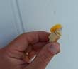
I made the inner plumbing ring around the radial dome out of brass tubing and used pieces of nyrod to make the 18 little extensions coming off of it. I used copper wire to simulate the plumbing from the cylinders to this ring, and little epoxy clamps were added and painted silver to strengthen it and add realism.
I made other miscellaneous parts out of hardwood, balsa and plastic scraps which really finished it off well.
|
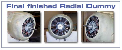
Well, here it is, my finished dummy radial built from the Frank Tiano mold. As I said earlier, the Tiano radial is 12 ounces out of the box... After cutting it to size and hollowing it out some, I dropped it to about 10.5 ounces. Then, after adding the backplate, mounting hardware, painting and 3D detail, it went back up to about 13.5 ounces. So overall, I only gained about 1.5 ounces to get it from a raw white plug to the finished product.
I can't wait to see it with the cowl all painted and weathered... should look real enough to hear it rumble on the deck!

"Laser Woes"
|