|
|
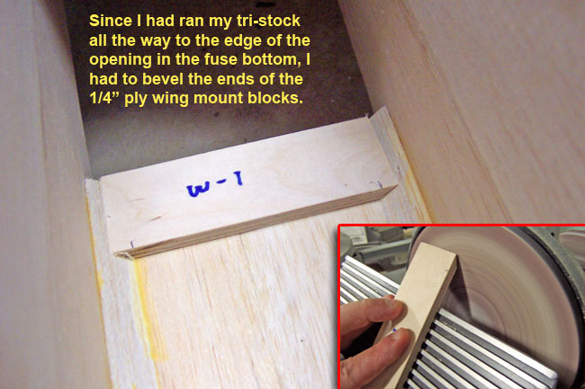
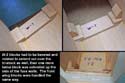
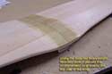
Adding the mount blocks in the fuselage
The supplied plywood wing mount blocks (W-1 & W-3) can be glued onto the floor inside the fuselage all the way from sidewall to sidewall if you stopped your tri-stock short of these areas. I however, ran my tri-stock all the way to the edges of the floor at the bottom opening. This meant I had to use a bench sander to bevel the mount blocks at an angle that would mate to the tri-stock.
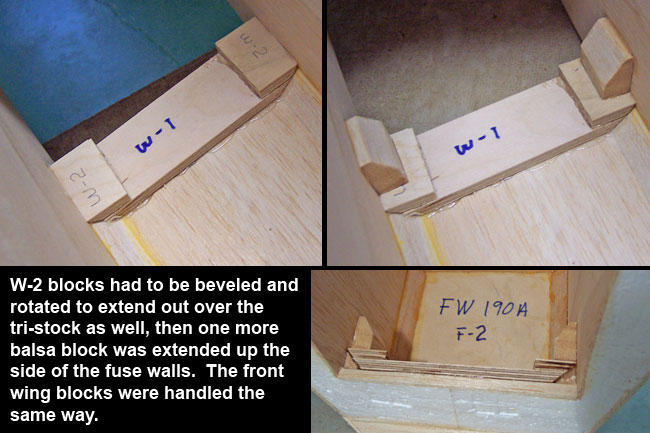
Likewise, the W-2 support blocks would run vertically up the sides of the fuse with right angle joints. On mine, I rotated them and laid them on top of the mount blocks, beveling them to the tri-stock as well. I then added one more large block of balsa stock on top of the assembly gluing it solid to the sidewalls. The front W-1 and rear W-3 blocks were both done this way. I may decide to go back inside here and reinforce with fiberglass later.
|
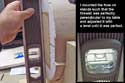
Leveling up the fuselage
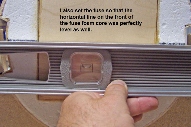
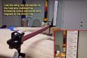
The first step to getting a straight wing mount is getting the fuse secured to the table perfectly level and straight. I set mine up in fuse stands checking for level at the firewall. The first objective was to get the firewall level on the Z axis. Since this kit calls for zero degrees engine thrust, the firewall is perfectly perpendicular to the airframe thrust line. That means that I can use the firewall as my zero-reference point for all measurements. If the firewall Z-axis is level, then I know my thrustline is level from nose to tail.
Next I check the crosshairs that came drawn on the X & Y axis of the nose of the foam fuse core and adjust as needed to get the fuse level from side to side. I secured the fuse and now know it's level and square to line my wing up to.
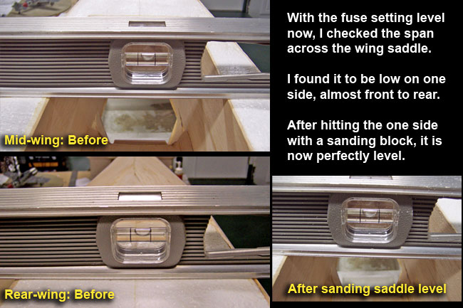
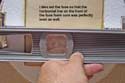
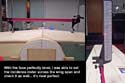
Now I check the level of the wing saddle opening from left to right side. Since the fuse is level, this opening should be level from left to right as well. I found one side to be a little high, mostly from the mid-wing back to the trailing edge. I just sanded it down on one side until I could get a perfect level reading from left to right the full length of the saddle.
|
|
|
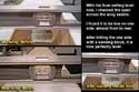
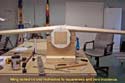
Aligning the wing
You may choose to go ahead and add the fiberglass reinforcement strip to the center wing joint before aligining the wing, but I wanted to check alignment first to see how close I was. If I was too far off, I wanted to correct it before going much further.
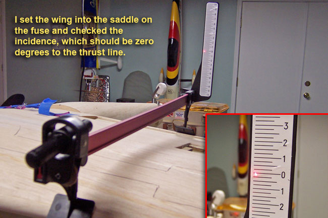
I frequently double-check the fuse for level to make sure nothing has slipped/moved, then get out my laser wing incidence meter. Again, since the fuse is level, I can zero out my incidence meter by setting it on a perfectly level area of my table and setting the zero point. Then it's ready to check the wing.
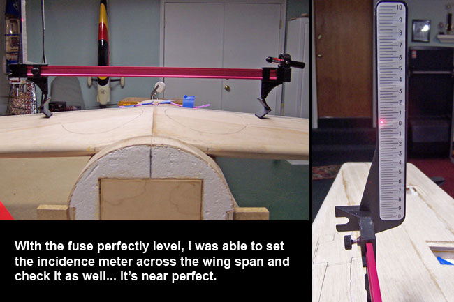
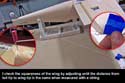
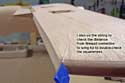
Checking the wing at about 12" out from the fuse I found both sides to be off by just a little. Sanding the saddle some more allowed me to slowly get the incidence nearly perfect. Also, since the fuse is level on the X axis, I could also lay my incidence meter across the wingspan to check it for level in that direction as well... which it was.
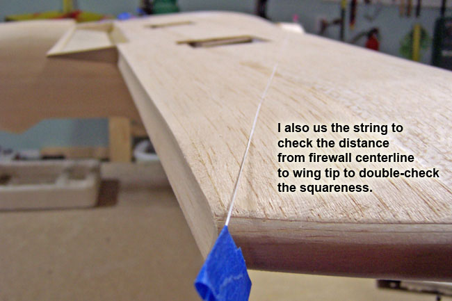
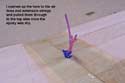
Lastly I check for "squareness" of the wing to the overall airframe. I do this by pushing a pin in the nose and tail of the plane right on the centerline. Tie a string off to the pin and stretch it out to a wing tip. Mark the measurement on the string with a piece of tape, then swing the string on over to the other wing tip. If they measure the same, you're wing is square. If not, adjust the wing as needed and repeatedly measure until the distances are the same. I measure this from both the nose and tail, then pen some guide marks on the wing and fuse so I can use them to align quickly again later. |
|
Adding the fiberglass reinforcement strip
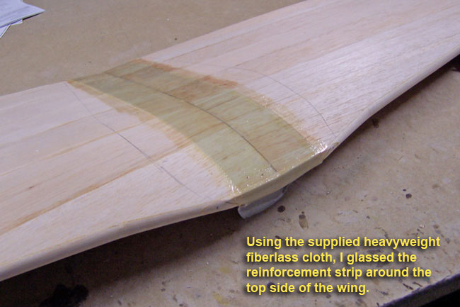
Ok, I feel my wing is lining up pretty good, so I go ahead and pull it back off to add the fiberglass reinforcement strip to the center wing joint on the top side of the wing first. Use the heavyweight fiberglass cloth strip supplied with the kit and apply it with epoxy. Thin the epoxy down a bit with some denatured alcohol or acetone. Be careful with acetone around styrofoam though, it will melt it.
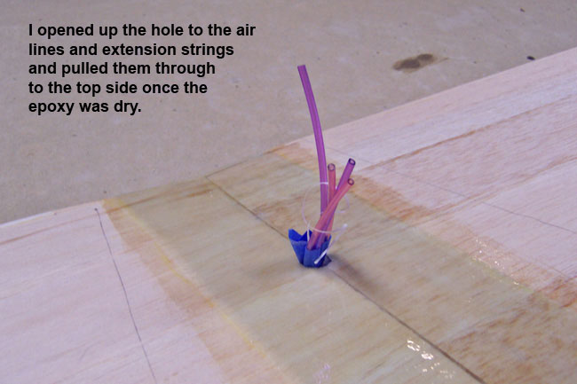
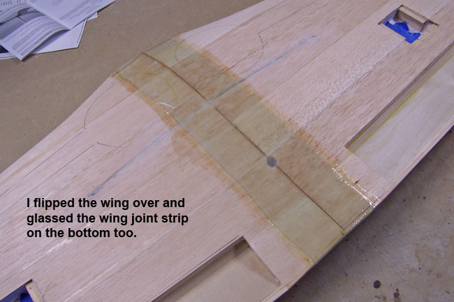
With the top side done first and the epoxy dry, I open up the access hole on the centerline of the wing and pull my airlines and extension lines up through to the top side of the wing (secure them off). Then, just flip the wing over and repeat the process on the bottom side of the wing.
Once the epoxy is good and dry on both sides, cut off the excess cloth and sand it down as needed for a relatively smooth surface. These areas will all get covered up so you don't have to be perfectly smooth. |

|
|
Re-align and mount the wing
I forgot to get a picture of this, but the next step was to go ahead and drill out the holes for the two wing mount dowel rods... one at the front and one at the rear. The difficult part here is that you want them on the centerline, but that's where the epoxy glue joint is. So, the drill bit will keep wanting to push off to one side or the other of the joint. I just offset the holes slightly and quit fighting it.
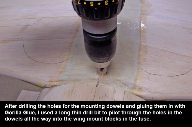
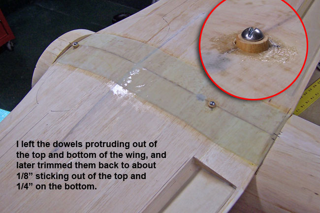
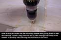
Once you have your dowels fittting well, you can glue them in leaving the excess length sticking out the top and bottom of the wing. I glued mine in with Gorilla Glue to make sure it filled out into all voids. I cut my dowels down on both sides of the wing so that I had about 1/8" sticking out the top side and 1/4" sticking out the bottom.
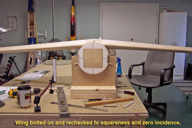
The next step was to re-cradle the wing in the saddle, align it to the guide marks and double-check all of your square/level measurements. All should still check out fine, so go ahead and secure the wing to the fuse with lots of low-tack masking tape. Run a long drill bit down through the pre-drilled holes in the dowel rods all the way into the mounting blocks in the fuse.
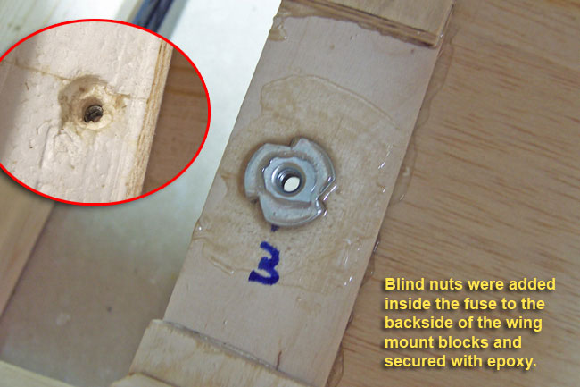
Pull the wing and enlarge the holes in the mount blocks to receive blind nuts. Insert the blind nuts into the holes and draw them down. I add epoxy over my blind nuts to help keep them from spinning or popping out. Once everything was good and cured, I bolt the wing on again and recheck everything for squareness and incidence.
|
|
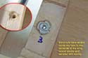
Final steps
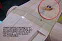
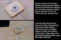
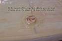
Last steps were to finish off the dowel stubs that stick out the bottom side of the wing. This is where the bolt heads will draw down, so I want to strenthen this area and spread the load out a little.
On the bottom side trailing end of the wing, I cut a large rectangular washer from 1/8" light ply and drilled out the center to slide over the dowel stub. With it epoxied in place, I added a metal fender washer on top of the area and glassed it all in with a square of 3/4oz cloth.
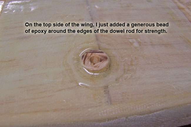
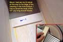
The leading edge mount was treated the same basic way. The difference was that due to the airfoil contour, I had to cut the wooden washer with a wedge shape to follow the shape of the front of the wing. I also added a good bead of epoxy around the dowel stubs sticking out the top side of the wing to add strength. One final remount and recheck of all measurements and I'm good to go.
I wil later have to build wing fairings and finish off the underside of the wing saddle. I'll also have to build a slight/thin belly pan on the underside of the wing to blend it into the fuse from LE to TE. But, for now, that's it for the wing.
|
|
|
|

"tailgear installation"
|
|