|
|
 |
|
|
|
|
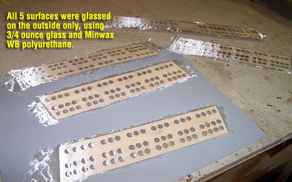
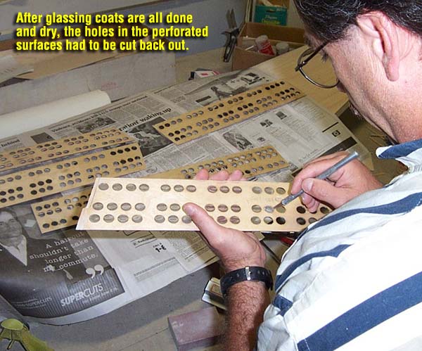
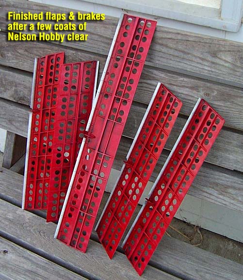
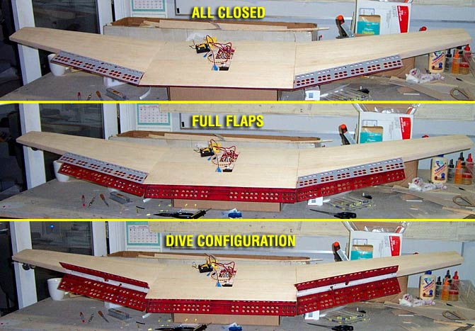
Glassing & Sealing the Flaps & Brakes
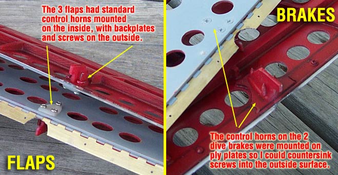
Control Horns and Hinges With the glassing cured, primed and sanded, I proceeded to add hinges and control horns. This proved to be quite interesting, since I was going for the most scale appearance I could get, balancing the difficulty and dependability factors into play. I wanted to get a good scale hing look from the outside, and hide as much of the control linkage internally as possible. My choice was to go with metal piano hinges from Nelson Hobby. They come in various widths and lengths so I got four 5/8" by 24" hinges and one 5/8" by 36" hinge. I also used standard heavy duty nylon control horns that were mounted in one of two different configurations. I cut the piano hinges to length for each surface and notched them out where the control horns/linkages would go. I then scuffed them up well with 320 sandpaper and epoxied them into place on each surface. I also pinned the hinges into the surfaces using about 4 servo screws on each hinge. Next I cut down 5 control horns to provide "short horns" with only one hole left, and positioned them into place on each surface. Since the 3 flaps are on the bottom of the plane, and the 2 brakes are on the top, I mounted their respective horns a little differently...
For the flaps, I mounted the horns on the inside, sandwiching the ply flap between the horn and the nylon backplate that mounted on the outside. I used standard 2-56 screws to secure them in place. Since the screw heads and backplates were on the bottom of the plane (less visible), I didn't mind the fact that they were external. Also, they're low profile and white, and the bottom of the plane is white... not too intrusive. Dive Brake horns... As for the brakes, that's a different story. I didn't want the backplate and screws sticking out externally on the topside of the wing so I used a different mounting technique. I cut a 1/16 ply plate about 1/4 inch larger than the base of the control horn and epoxied it to the inside of the brake. This allowed me to countersink sheet metal screws into the outside of the brake and still have something for the threads to "bit into" before threading into the "inverted" horns themselves. This provided me with a solid mounted horn, but gave me 3 flush screw heads on the topside of the brakes. I can putty and paint right over them and you'll never see them. Painting the inside surfaces
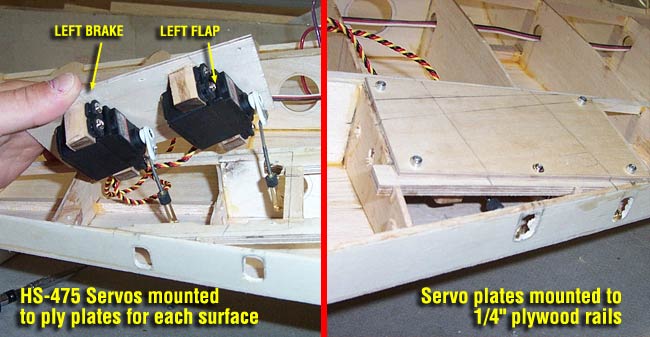
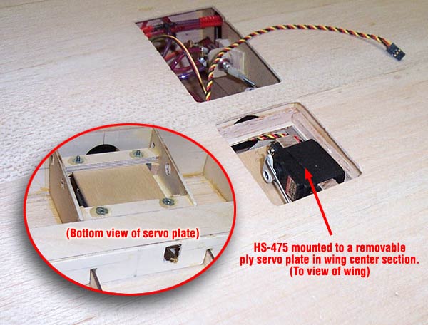
Redesigned "5-Servo" Configuration/Mod
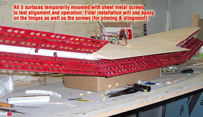
Temporary "Mounting & Operation" Test
Temporary "Mounting & Operation" Test
Conclusions... My biggest issue/complaint with the flaps and brakes are the "droop 'n' warp" factor. Since they are built out of very large pieces of only 1/16" light aircraft ply, they tend to bow, droop and sag a little differently on each surface. This means that they really don't "seal" together perfectly across the full length of the trailing edges of the brakes. The flaps and brakes pinch together tightly at the trailing edges in some areas, the droop to a 1/8 inch or so gap in other areas. Also, they don't always seem to "settle" to the exact same position every time, especially depending on whether the wing is upright or inverted. I'm probably being a little "anal" on this, since the photos I've seen of other RC scale Dauntlesses seem to have the same issue. I'm sure it would be less of a problem for those who have elected to have "fixed/non-operational" dive brakes, since that's one less surface to deal with. Maybe digital servos & servo programmer, or a Matchbox might have helped a little too, but it's not worth the expense. Ultimately, the light ply would probably still droop and bow a little any way. Every piece of 1/16 aircraft ply I've ever seen over 12" long has always had some bow or warp to it, I don't know how you could ever get it to lay perfectly level and true within 1/16 inch tolerance when you're anchoring it on only one side. The very small ribs and the 1/4" balsa spar don't really provide enough support or rigidity to this design to effectively hold it flat. The weight and warp of the ply itself tends to overpower the ribs and spar in my opinion. My final take on this setup however is very positive. I like the 5 servo setup much better than the 2 servo/bellcrank system. It's much stronger, more precise and just a cleaner setup. It weighs a little more, but not enough to hurt. Bottom line is this... standing behind that wing and flippin the "Dive Brake Switch" on my radio, watching all 5 of them big ol' red surfaces jump into position is just WAAAAAAY COOL!!!!!!!! UPDATE: The most recent version of the Bates plans still has the bellcrank system, but has been redesigned. It uses 4 servos now, 2 for flaps and 2 for brakes, and has moved forward to a position between the front and rear dihedral braces. I like my 5 servo system better (so far) but it would be nice to not have the access hatches I have to use.
|