From the Waterline Crutch and Up
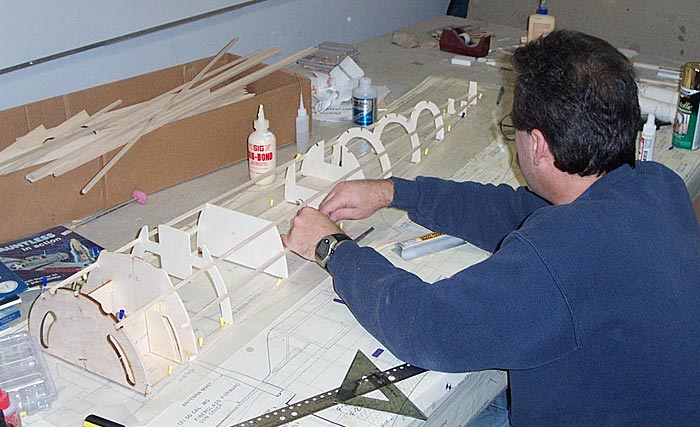
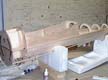
Again, since I'm building the fuse without having the motor yet, I'm just going to take it so far at this point. Like building the tail secton, the fuselage is built by framing it up on the plans, starting with the "waterline" crutch and working up. Once done, you again sheet it, and flip it over, to build onto the top half... completing the bottom side of the plane. Therefore all your formers will be cut horizontally in half, giving you a top and bottom half to each former.
After building my SBD, and seeing the latest version of the Bates plans, I found that Jerry has redesigned the fuse completely. He has added a lot more scale detail, made the lines more accurate, and included the wing fairing into the fuse formers... big improvement!
|
The plans have you sheet the top half of the fuse before removing it from the building board & plans. This helps make it more stable/rigid after removing, so that the fuse stays straight & true when you flip it to build the bottom half.
Since I didn't have the motor yet, I sheeted up to the cooling vent slots just behind the cowl. This left me access to the area inside the fuse on the backside of the firewall for later engine mounting. Also, I didn't want to sheet completely over the former bay under the rudder, since I knew I would have to get in there later to hook up my control linkages.
|
The Gun Storage Compartment
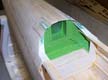 |
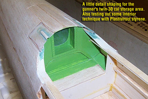
While this pic shows the back wall and gun storage area after sheeting the fuse, I actually built this section before sheeting over it for obvious reasons. I built the storage box out of balsa, and constructed the back wall from Plastistruct styrene. This pic shows it with just a base coat of a random green color to be painted over later.
|
Note that I built "static" barndoors on the top of the storage box, they won't open but will have a strong 3D relief that will show up after glassing. I also built the two sliding doors on either side of the barndoors. I think these were slid back out of the way to access the sides of the twin 30 cal gun, maybe to load and unload the ammo belts.
Adding the Tail
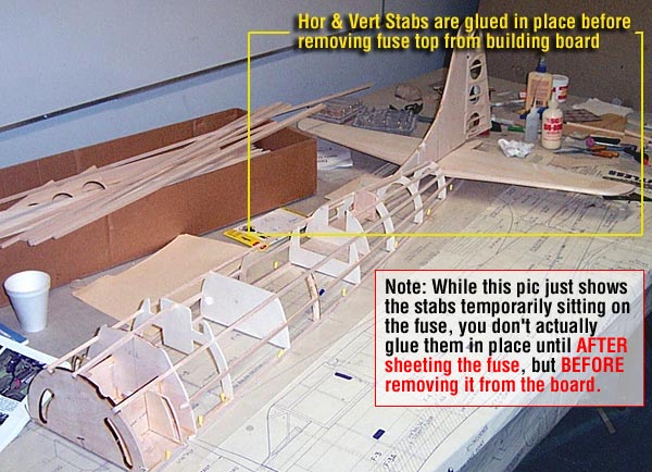
Once you have the top half of the fuse sheeted (3/32" sheeting), you need to go ahead and glue the horizontal stab and vertical fin into place with epoxy.
Test Fit |
This allows you to make sure that you have the stabs mounted perfectly square and parallel to the waterline of the fuse and each other. It's easy to take measurements at this point and adjust while the slow-curing epoxy sets. Once it's dry, you remove it from the board and flip it to start on the bottom half.
|
|
Flip the Fuse
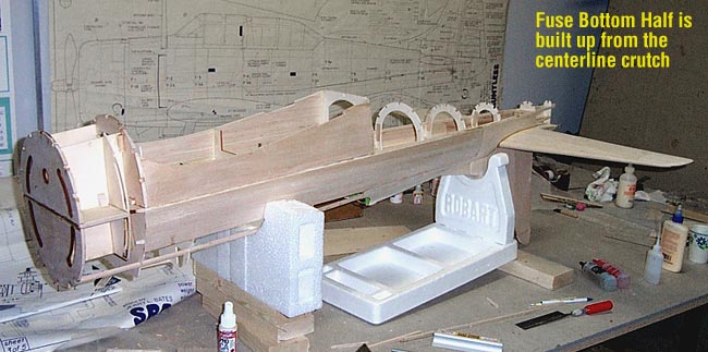
Now you can flip the fuse over and begin working on the bottom side. You'll build the bottom half of the baffle/engine box, add the wing saddles, the cockpit floor, servo tray, and eventually tackle the "planking" of the rear section.
|
|
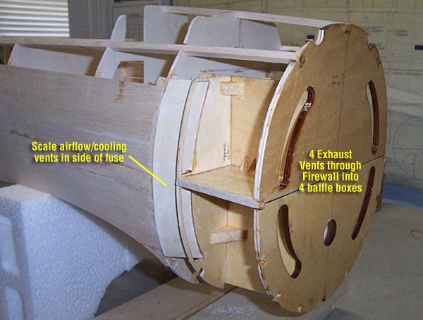
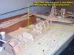
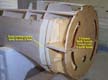
You can see in the pic shown at left here, how the 1/4" plywood firewall has four exhaust vent slots cut out of it. These slots are designed to feed the exhaust from a stock muffler setup back through the firewall, into four "baffle boxes" and out the two scale cooling vent slots in the side of the fuse.
The baffle boxes, made of 1/8" light ply, also form the standard "engine box" that backs up and reinforces the firewall. Note that I have not yet added the top and bottom plate of the baffle/engine boxes, since I'll still need to get in there to mount the motor later. I'm also adding a substantial amount of triangle stock and other reinforcements in this area to make it as strong as possible. All of this area gets fuel-proofed with epoxy resin.
|
Tailgear and Control Linkage
The tailgear and control linkage was actually done at this point, however I decided to move the explanation to it's own separate page... Tailgear and Control Linkage. It's the next page, so you may just want to read on here.
Planking the Belly
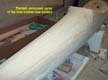 |
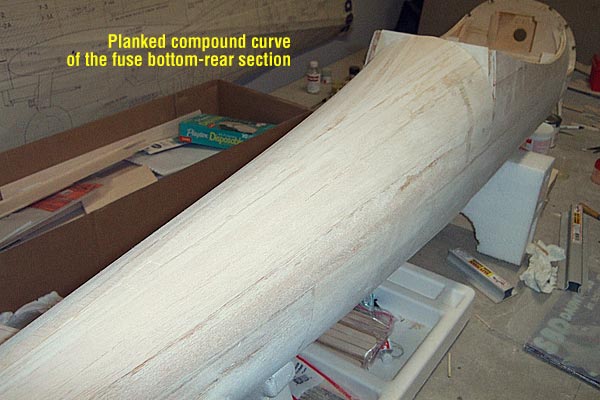
While I used standard sheeting techniques to sheet the top of the fuse, I had to plank the bottom rear "belly" section (from the wing TE back) due to the compound curves. This was my first crack at planking, so it was a learning experience. I'm pretty happy with the way it turned out, but I'm sure I'll get better on each planking job I do.
.
|
The Tail Cone
|
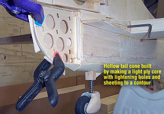
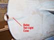
The plans tell you to simply build the final "Tail Cone" out of hollow balsa, but don't exactly tell you how to go about it. Nor did I find any special stock for this in the laser-cut kit. I decided to use the thin plywood core approach to establish the profile of the tailcone (template-cut from the plans). I forstner bits to cut out lightening holes in the core, but maintained good strength to the structure.
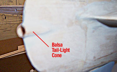
Next, I glued some small balsa "backplates" to the last former and proceeded to sheet the two sides of the cone with 3/32" balsa. Once this was done, I cut out a small section where the tail light goes. I carved the tail light "teardrop" out of balsa with a groove down the center of it. I slid the groove over the tailcone cutout and blended it together with Squadron putty.
|
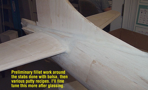
Blending the Stabs
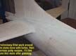 |
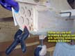
The fuse sheeting stops abrubtly right at the LE of the hor stab and leaves a large open area between the the hor & vert stabs that needs filled now. I started out by hand carving a large balsa block to try to form the feathering teardrop halves that would complete the lines of the fuse back to the tail cone. After gluing them into place and sanding them to as accurate a shape as possible, I began making small fillets out of 1/4" triangle stock to blend the stabs into the fuse.
Getting this as close as possible to proper shape, I smoothed it out further with a mixture of epoxy and microballoons. Lastly, I feathered it out even more with Squadron putty, including a feathered trailing edge on the "T" section of the hor stab where it meets the tail cone. I plan to smooth & feather this all even more after glassing.
.
|

"Tailgear & Control Linkage"
|