|
Sept 10 , 2006
Retract air tank installation
I would normally install something as light as the Robart retract air supply tank back further in the plane as it would give more room up front without messing up the CG too much. However, since I plan to add a cockpit, I'm finding things are just getting too crowded inside the fuse back there and I don't want conflicts with the pull-pull or pushrod linkages.
So, what I ended up doing is mounting it up front, just behind the firewall, but recessed it halfway down into the wall of the fuselage (taking much less room). To do this I cut a groove out of the inside "ceiling" of the fuse the same shape and size as the air tank. I then lined the trough with 1/16" balsa sheeting and came up with a Velcro strap that would secure it in place. Simple, effective and out of the way. |
|
| |
|


|
Fuel tank assembly
Assembly of your fuel system will vary dramatically from tank manufacturer to tank manufacturer, but all are relatively the same. The biggest issues are whether you are doing a "2-line system" vs a "3-line system" in your bird, and whether you are using gasoline vs glow for fuel.
Without going into great detail or debate, the short and skinny is that I prefer gas power, especially on planes of this size... and, I prefer "3-line systems" that have a dedicated third line for refueling as opposed to using a "T" in the carb/supply line to the engine. The 2-line systems have extra joints in the pressurized lines that can leak and cause problems. Also they have the potential of leaking at the fuel dot/cap where you fill the tank (bad news).
Of course, there is also the issue of gas engines having a pump in the carburetor, so tank placement is less critical than with glow engines (unless an external pump is used on the glow engine).
|
|
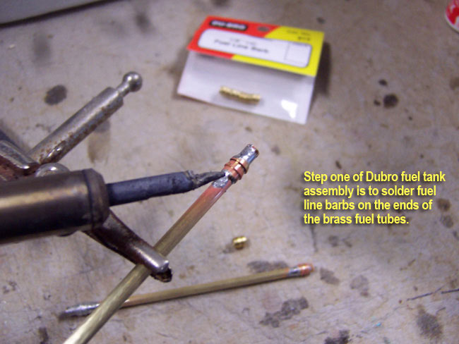
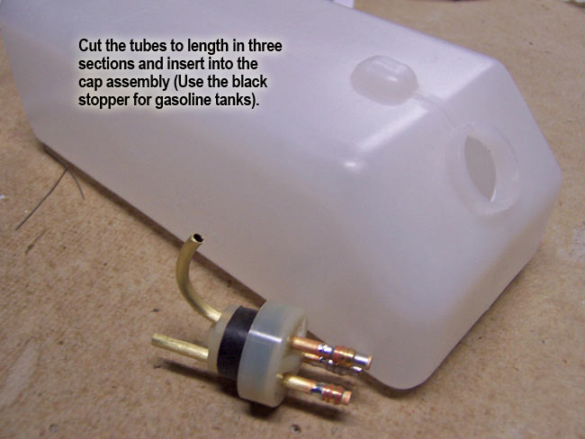
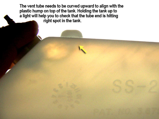
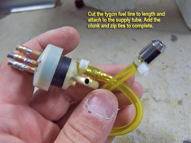
Anyhow, moving on... I start by soldering Dubro's brass barbs onto the ends of the brass fuel line tubes to make the tygon lines fit better. I then put the three brass tubes into the fuel tank cap assembly (use the black stopper with gas engines, not the white one). The Fill tube just needs to stick inside the tank about 1/4" and the Vent tube needs to be pretty long. Curve the vent tube upward so that it sticks into the "bubble/hump" at the top of the tank. You can check this by holding the tank up to a light to see the tube alignment with the vent bubble on top.
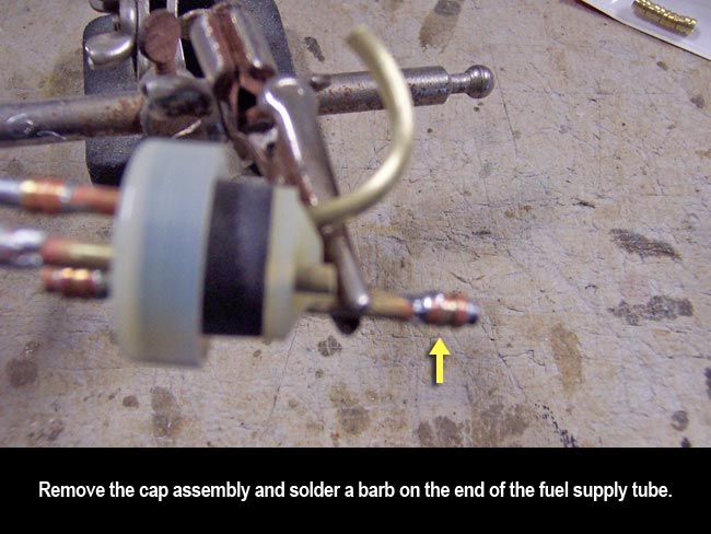
Now remove the cap assembly and solder another barb on the inside end of the carb/supply line tube. This should be about a half inch long inside the tank. Get out some of the yellow Tygon fuel tubing (for gasoline) and add the clunk to one end. Mount the tubing over the supply barb and test fit everything back in the tank.
You want to make sure that when holding the tank up to a light, you can see the clunk swing freely all the way to the bottom end of the tank... yet not get "hung up" at any point when rotating the tank around in various orientations. If the tube is a little long, trim until the fit is right. If it's too short, get your "tube stretcher" out. LOL, just kidding... throw it out and start with a new piece of tube!
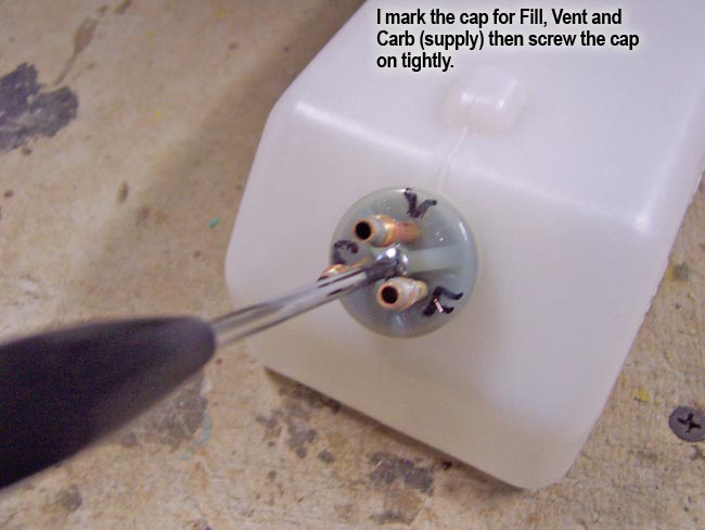
Now you can add some nylon zip ties over the tygon clunk line to secure both fittings well. Replace the cap assembly back into the tank and mark the cap as to what each line is for future reference (Carb/Supply, Filler, and Vent).
|


|
|

|
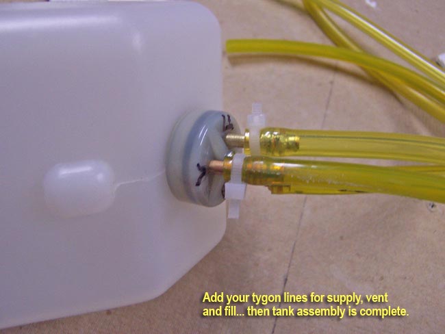
With all the internal tubes, lines and clunks installed in the tank, you are pretty much done with tank assembly. You ultimately need to cut the exterior Tygon lines to length and route them as well. When you are sure that you have all the routing and lengths worked out, you can add some zip ties to the external tube connections as well.
| Lastly, it's a good idea to put some fuel in the tank and plug up the ends of the Tygon tubes for a test. Let it set outside for a few days with the cap end tilted down to make sure that the tank, cap and/or lines are not leaking anywhere before installing in the plane. |
|
|
|
Fuel tank installation
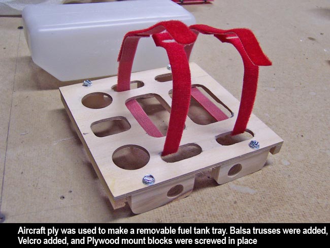
I'm installing the fuel tank in the front of the fuse, directly over the air tank, nearly dead on CG. It's always a good idea to put fuel tanks on CG whenever possible so balance doesn't change as fuel is run off during flight. First step is to build a tray to carry the tank.
I made the tray out of aircraft ply with liberal lightening holes cut out of it to minimize weight. Don't forget that you're mounting the tank upside down so that it is upright when you flip the plane back over onto its feet! I glue two Velcro straps to the tank for strapping the tank down. I then used four sheet metal screws to mount four plywood blocks under the tray. These blocks are screwed on so that they are flush with the left and right sides of the tray. I also added two thick balsa support sticks (at front and rear) on the underside of the tray, running from left to right. The stick has a curve cut out of the underside so that it rests perfectly on top of the air tank below it.
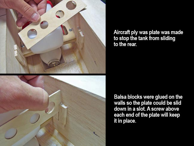
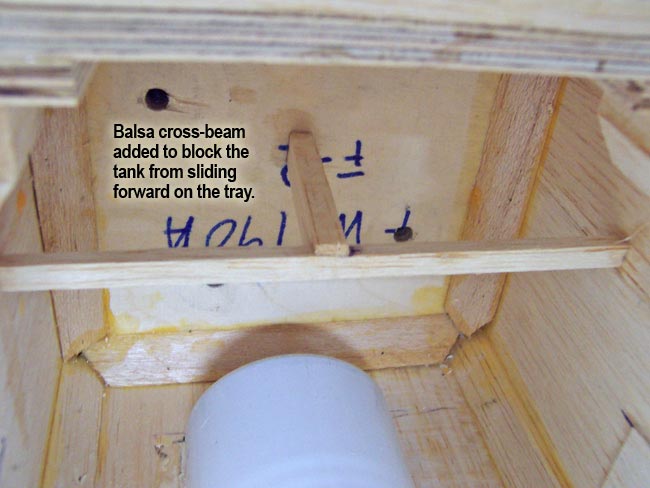
Before installing this assembly, I test fit and find the position the tray to glue some balsa trusses inside the front of the fuse to block the fuel tank from sliding forward in flight. Make sure they are not in the way of your engine mounting bolts.
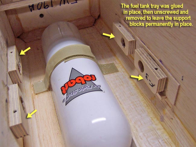
Now I go ahead and slide the tray assembly in place, gluing them to the left and right inside walls of the fuselage. Once the glue is dry, I could then remove the four screws and the whole tray slides out, tank and all. This leaves only the four blocks on the inside of the fuse giving me plenty of clear working access to the air tank and firewall.
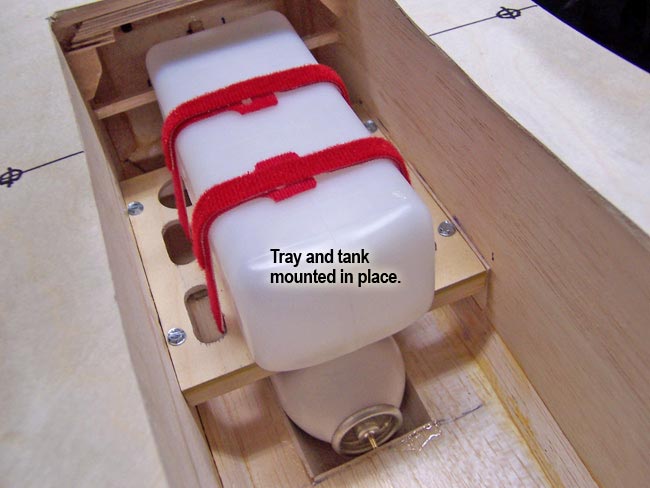
 Now I only need to remount the tank, strap it down and create a cross-plate that blocks the tank from sliding to the rear of the plane during flight. This was made from AC ply with lightening holes, and slides down into a slots formed by balsa blocks glued to each side of the fuse. This is easily removable as well and can be secured in place with a small servo screw above each end of the plate. Later I will cover where the fuel lines get routed. Now I only need to remount the tank, strap it down and create a cross-plate that blocks the tank from sliding to the rear of the plane during flight. This was made from AC ply with lightening holes, and slides down into a slots formed by balsa blocks glued to each side of the fuse. This is easily removable as well and can be secured in place with a small servo screw above each end of the plate. Later I will cover where the fuel lines get routed.
|


|
| |
|
|


|
Throttle installation
Throttle installation is pretty straightforward. Once I've worked out where the pushrod (Golden Nyrod) needs to run, I locate my servo position. Again, trying to use as little interior space as possible inside this tight fuselage, I decided to mount the servo inside the styrofoam wall.
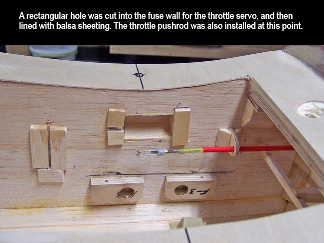
First I cut out a rectangular hole the shape/size of my Hitec HS-425BB throttle servo. The hole is lined with balsa sheeting to protect the styrofoam, and two AC ply plates are mounted to the fuse wall (one on each end of the hole). A slot needs to be cut through one of the mounting plates to allow the servo lead to slide down into the hole.
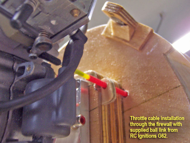
 Next I ran the nyrod through a hole in the firewall with AC ply alignment tabs slid over each end. The pushrod mounts to the carburetor linkage via a ball link that comes pre-installed on the RC Ignitions G62 engine. Next I ran the nyrod through a hole in the firewall with AC ply alignment tabs slid over each end. The pushrod mounts to the carburetor linkage via a ball link that comes pre-installed on the RC Ignitions G62 engine.
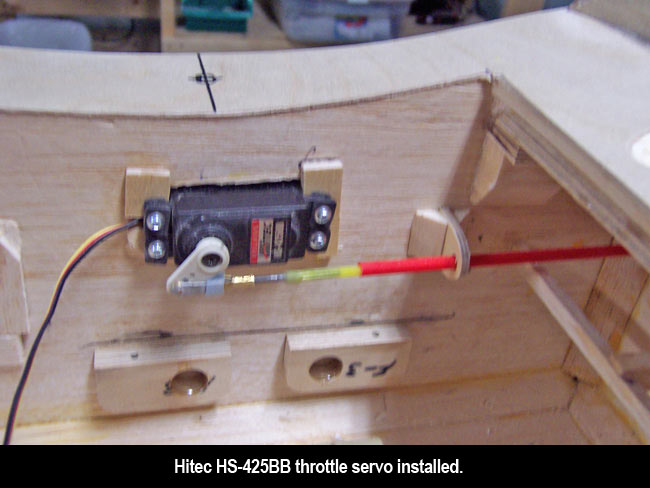
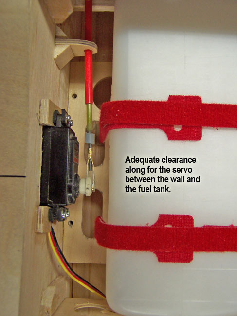
Last thing to do is go ahead and mount the servo into the hole in the fuse wall and secure it to the AC ply plates via four servos screws. The finished installation allows good clearance for the linkage and is far enough away from the fuel tank to eliminate any conflicts there as well. That's it for the throttle installation! |
|
|

"hardware installation"
|
|
